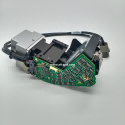
Today, I will share with you the maintenance experience of an ASM component camera
This is a No. 48 camera brought by our customer for repair
Now his camera's failure phenomenon is that the 42V power supply voltage is pulled down, causing the camera LED module to fail to work.
The connection terminal mainly receives 24 volts and 42 volts, and there are 4 sets of communication signals.
Among them, 24 volts is normal
The 42V LED light here is not on, indicating that the 42V is pulled down.
This 42 volt, it mainly supplies power to our three groups of LED light sources
24 volts come here and convert to 5 volts through this chip
Then through this MOS tube
Then convert it to 3.3 volts to power these main chips and logic ic
Then use this mcu to drive the control
Through these two communication chips
To control these operational amplifiers behind.
In order to realize the control of this light source.
I just measured the 42V with a multimeter and it was not supplied. This is actually
One of the chips is damaged.
All that remains is to find the faulty IC.

After replacing the IC, install the camera on the patch head, test it on the HCS instrument and run it for a long time. Only when the quality is stable and no error occurs can it be finally sent to the customer.
Now let's look at the results of the camera test after the camera is repaired. The camera is considered repaired.