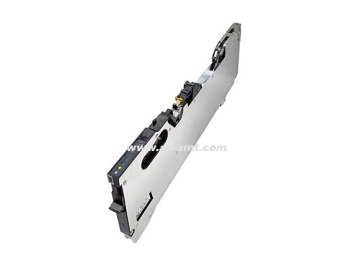
In the SMT factory, when the German ASM placement machine is working, the main factors that cause the abnormal operation of electrical components are: unstable input voltage of the power grid, abnormal shutdown, ambient temperature and humidity, dust and other factors; The frequent hot swapping of feeders and nozzle trays will also increase the failure rate of the FCU. Therefore, the temperature, humidity and dust in the workshop need to be monitored and optimized in real time, which can greatly reduce the failure rate of the equipment. Today, I would like to share with you the handling methods and maintenance ideas when the control core X-FCU of the feeder and nozzle changer of the X-series S series placement machine is abnormal. The correct part number of the X-FCU (slot40) is : 03096377 (old model), 03170613 (new model).

The following are the actual maintenance case maintenance ideas of the old X-FCU:
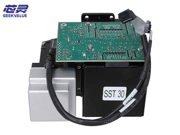
1. X-FCU is the control core of the feeder, the nozzle distribution plate and the cutter. It is mainly composed of the following functional parts:
1) Control of the feeder
2) Control of nozzle changer and waste box
3) Control of strip cutting
2. The X-FCU internal control board has the following parts:
Control Board-FBG_FCU-X: 03092560-03
*1) Control connector port description
X7: 26-28V voltage input, pin4-+26-28V input, pin2-GND
X3: canbus communication signal, pin2, 5: LGND/pin3: CAN_L/pin4: CAN_H
X4/13: Trolley safety lock
X11: Feeder Release
X23: Cylinder solenoid valve control for nozzle changer
X21-22: Scrap box detection sensor
X5-10: Cutter System
X12-13: Nozzle changer communication port
X26: 24V input
EDIF Control Board - 2PCS: 03115477-06 - Each board can control 20 8mm feeders.
Function description: These two cards are mainly responsible for the power supply communication control of the feeder
The common faults of X-FCU mainly include the following faults:
Can't power up
Canbus Communication Failure - Table xx subsystem not responding, unable to detect ISS version.
Repair ideas:
1) For the abnormal power supply of the FCU, check the power input terminals of X7 and 26 one by one. The 24V is directly connected to the LM3175 and converted into 12V. The output terminal of the LM3175 is used as the power input terminal of the 82F4 and is converted into 5V to supply power to the main control IC; the output of the LM3175 The terminal is used as the power input of the power chip 81J9, which is converted into 3.3V to supply power to the logic IC. The static measurement method can measure whether 24V, 5V, 3.3V and GND are short-circuited, so that most power supply failures can be judged.
2) Communication failure, just follow the pins 3 and 4 of X3 to find the receiving pins 6 and 7 of the canbus transceiver TLE6250G, find the pin 1 and 4 of the can chip by looking up the datasheet of the IC to find the main control driver IC, and measure the communication signal in real time through the oscilloscope The voltage waveform can be used to determine the specific fault point. The maintenance for the FCU can basically solve most of the faults here.
After all the above fault points are detected and the maintenance is OK, it is time to test on the machine. This is the maintenance idea of Xinling Industry for the X-series mounter X-FCU. If you have different opinions, welcome to communicate more! Xinling Industry is a company focusing on providing a full range of one-stop solutions for ASM placement machines. It has been deeply involved in the placement machine industry for 15 years, providing ASM placement machine sales, leasing, spare parts supply, equipment maintenance, and board motor maintenance. , Feida maintenance, patch head maintenance, technical training of a full range of business!