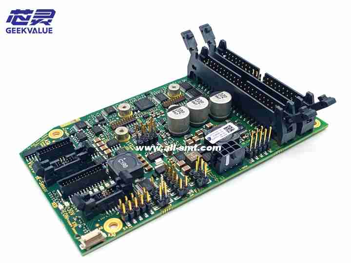
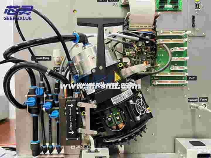
ASM's latest generation of high-speed, high-precision placement head CP20 P2 (03126608), its efficient placement performance is favored by customers, CP20 P2 is mainly used on TX/SX/XS machines, P2 placement head (03126608) as an upgrade of CP20P placement head version, the major changes include the following components:
Vacuum generator 20P2 (03136795)-20P (03106620)
Star Motor 20P2 (03131704)-20P (03106227)
Z-axis 20P2(03122923)-20P(03091161)
Head interface board (03134908)-20P (03110751)
The Adapter board CP20 P2 (03134908) has changed the control mode of the previous shield boards. Strictly speaking, the previous 20A/20P are all head board adapter boards, while the Adapter board of CP20P2 patch head has changed from normal. , is a multi-functional control board that integrates transfer, control, and power conversion. Therefore, today I will share with you an actual maintenance case of the CP20P2 Adapter board.

ASM patch board CP20P2 Adapter board 03134908
Fault phenomenon: When the z-axis motor returns to the reference point, an error occurs when the z-axis motor returns to the reference point.
Fault description: The shield power supply and communication are normal.
Fault analysis: According to the logical sequence of the normal return to the reference point of the placement head: Z axis return to the reference point - Star axis return to the reference point - Z axis return to the reference point - protection cylinder lay down - DP return to the reference point. The phenomenon we saw when we tested the machine was that after the Star axis returned to the reference point - the Z axis moved slightly up and down - and then an error message appeared that the accuracy of the motor was not enough when returning to the reference point, so we can judge that this is the cylinder power supply The port has no 24V output caused by the error.

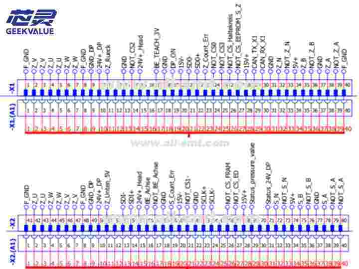
The shield access port is defined as follows:

First, let's explain the port definition of the shield board:
It is not difficult to see through the above ports that the pin42-47 labeling of X2 is wrong, and the correct one should be S_U/V/W.
From the above picture, it is not difficult to see that the motor power supply of the Star axis/Z axis and the interface end of the encoder are directly drawn from X1/X2.
X1pin2-7 is the Z motor wiring, X1pin32/35/38 are the three square wave outputs of the Star axis encoder
X2pin42-47 are the wiring of the star motor, and X2pin72/75/78 are the three square wave outputs of the star shaft encoder.
The trigger signal of pin11-Z-rueck of X1 to protect the cylinder is sent by the MHCU. The premise is that after the Z motor returns to the reference point normally, the CPU of the shield will output a Z-axis OK signal to the MHCU.
Maintenance ideas: First of all, when the power supply and communication are normal, it is difficult for us to directly measure whether the power supply voltage of each IC is normal by powering on, because the measured results are also normal. At this time, it is best to compare the static impedance value of the pins of each IC through the static measurement comparison method to determine whether there is a fault. Through measurement, we found that the resistance of several pins of the LCX138 IC is a bit low compared to the resistance of the normal board. Therefore, we dismantled the IC and measured it again, and it was still low. Through unremitting search, we finally determined the fault of the main control CPU, and this fault point was solved.


