ave up to 70% on SMT Parts – In Stock & Ready to Ship
Get Quote →An advanced technical manual for troubleshooting ASM SIPLACE 8mm X-Feeders and S-Feeders. Leverage factory-grade diagnostics to fix pick errors, index jams, and motor timing wear while optimizing your SMT line's long-term OEE.
Get instant quotes for high-precision components or backup calibrated feeders verified by our laboratory engineers.
In continuous high-CPH surface mount assembly lines, minor mechanical wear inside a feeder can amplify into extensive component rejection. Our factory maintenance lab has compiled the 10 most critical failure modes for the SIPLACE 8mm series, complete with standard engineering actions:
| No. | High-Frequency Symptom | Probable Root Cause | Recommended Technical Action |
|---|---|---|---|
| 01 | Frequent Pick Errors (>0.03%) | Shutter blade mechanical abrasion or fine component dust buildup causing tiny timing latency. | Flush the shutter channel with isopropyl alcohol. Replace the shutter blade if deep friction wear is visible. |
| 02 | Carrier Tape Index Jams | Sprocket teeth wear or fatigue in the internal tape advancement gear spring tension. | Examine sprocket profiles under magnification. Swap in high-durability replacement springs or the sprocket wheel. |
| 03 | Tape Feeding Pitch Mismatch | Brushless stepping motor overheating or skipping encoder steps under continuous load. | Verify current stability on an offline tester. If step offsets repeat, replace the motor assembly. |
| 04 | Nozzle Scrapes Component Tray | Deformation of the feeder's Z-axis reference plane due to harsh mechanical impacts during trolley loading. | Check planarity on a calibrated measurement jig. Replace structural casting if structural bending exceeds ±0.02mm. |
| 05 | RFID Identification Failure | Oxidized or contaminated gold-finger interface contact pins on the feeder base. | Clean interface contacts with an anti-static microfiber cloth and contact cleaner. Replace the emulated chip if data fails. |
| 06 | Cover Tape Peeling Faults | Worn-out collection gear friction plate or broken internal take-up torsion spring. | Recalibrate take-up assembly torque. Replace the collection spring to restore consistent peeling tension. |
| 07 | Intermittent Electrical Disconnects | Internal wiring harness micro-cracks or loose connection sockets caused by long-term high-speed vibration. | Perform continuous conductivity testing across the internal harness. Rewire or replace with vibration-resistant cables. |
| 08 | Component Flipping inside Tape | Improper clearance setting on the cover tape peel blade or localized static charge accumulation. | Adjust the tape guide blade height to match tape specifications exactly. Verify grounding line continuity. |
| 09 | Sprocket Forward Over-Stepping | Failure or wear of the mechanical anti-reverse braking pawl inside the indexing housing. | Inspect the braking lock mechanism. Replace the lock pawl component to prevent tape over-advancement. |
| 10 | Optical Sensor Read Errors | Opaque film of industrial oil residue covering the home-position optical sensor lens. | Carefully clean the sensor array with an anti-static cotton swab. Replace the sensor module if signal output remains weak. |
Struggling with complex throwing issues? Send your units to our specialized factory calibration lab.
Consult Our Repair EngineersRather than repairing hardware after an active failure occurs, high-performance SMT lines implement rigorous preventive maintenance intervals to control throwing rates and optimize tool lifespans.
| PM Interval | Key Maintenance Actions Required | Target Performance Standard |
|---|---|---|
| Weekly (On-Line Inspection) | 1. Wipe down the external gold-finger contacts with a dry anti-static cloth. 2. Clean the component pickup window with a specialized air-jet to remove loose debris. |
Zero data-bus communication drops; smooth mechanical shutter actuation during high-speed runs. |
| Monthly (Off-Line Servicing) | 1. Disassemble the shutter blade casing and clear internal micro-dust. 2. Inspect the indexing tape drive gears for structural residue accumulation. 3. Apply minimal high-vacuum lubricating oil to the primary pivot pins. |
Frictionless manual tape feeding; zero stutter or lag in the shutter opening and closing cycles. |
| Semi-Annually (Full Overhaul) | 1. Replace common wear items including the tape-advancement spring and cover tape take-up spring. 2. Run a full 1,000-cycle diagnostic routine on a dedicated calibration tester. 3. Check the pick-point position alignment tolerance (≤ ±0.02mm). |
Re-certified feeder performance matching original factory parameters; pick error rate under 0.03%. |
Don't let an accumulation of damaged or high-throw-rate feeders bottleneck your assembly output. Our state-of-the-art repair center provides comprehensive, high-precision refurbishing and engineering calibration for all ASM SIPLACE 8mm feeders, backed by specialized laboratory equipment and elite technician teams:
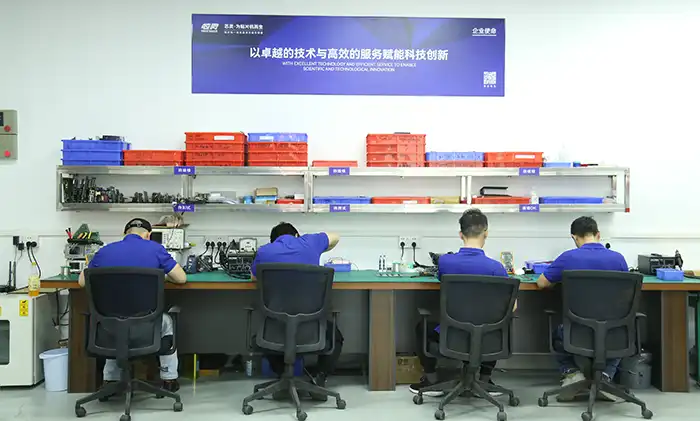
Time is money on the SMT floor. Our maintenance laboratory operates on a continuous, round-the-clock dual-shift framework with more than 20+ full-time technical specialists. This non-stop operation ensures that once your faulty feeders arrive at our facility, they are diagnosed, rebuilt, and prepared for return dispatch within a highly compressed timeframe to keep your line running.
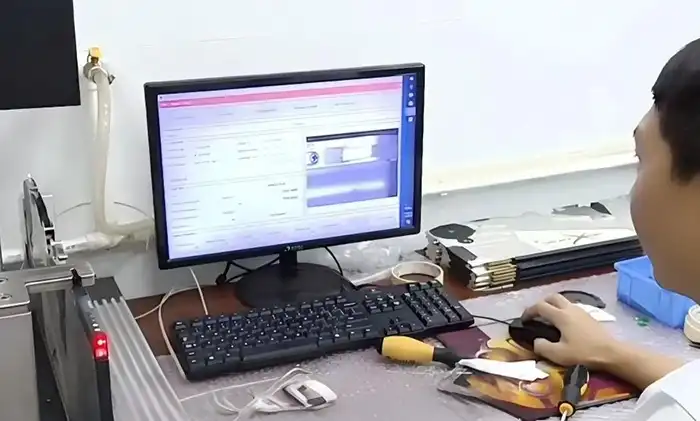
We do not rely on speculative manual alignments or guesswork. Our testing facility is equipped with dedicated, high-precision original SIPLACE software verification testers. Every repaired unit undergoes a demanding 1,000-cycle high-speed dynamic stress test to strictly verify step consistency and timing parameters down to a tolerance of ≤0.02mm before passing inspection.
Your high-value automation hardware is handled with true industrial expertise. Our core repair team consists of senior SMT specialists who previously worked directly within OEM manufacturing and technical service divisions. This extensive ex-OEM field experience guarantees deep-level mechanical mastery, precise firmware synchronization, and factory-standard troubleshooting for complex structural alignment failures.
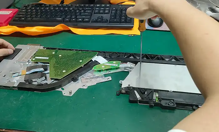
Whether you need a single critical unit diagnosed or a batch of 50+ feeders structurally overhauled before a high-volume manufacturing run, our 24/7 laboratory is scaled to handle your technical load. Every serviced feeder leaves our floor accompanied by a verified pick-yield certificate ensuring error rates under 0.03%.
Stop wasting precious engineering billable hours on unstable, onsite patching. Outsource your hardware maintenance to our high-capacity repair facility and experience factory-fresh precision with elite 24-hour delivery tracking.
Book a Batch Feeder Repair AuditThe single most prevalent cause is mechanical micro-friction on the shutter blade assembly or micro-dust buildup inside the shutter channel. This causes slight delays during the exposure window, leading to misaligned pickup actions by the machine nozzle.
Initial signs include atypical heat generation during short runs or occasional feeding errors on the test jig. When mounted to a tester, a failing motor will show minor deviations in step consistency that exceed the native ≤0.02mm limit.
Yes. Contamination or oxidation on the bottom interface pad interrupts data transfers with the trolley bus. This can prompt sudden machine alarms, barcode drops, or failure to recognize the unit's RFID identity.
No. Standard lubricants attract solder paste powder and fiberglass dust, creating a compound that can seize tight tolerance tracks. Only specialized high-vacuum industrial oils should be used sparingly on critical pivot points.
Under a typical two-shift high-volume operating environment, common internal tension and advancement springs require proactive replacement every six months to prevent sudden loss of tape indexing torque.
This typically indicates a planarity fault where the feeder's main aluminum frame has bent slightly due to rough handling or dropping. These structural issues require realignment on an engineering jig.
Premium compatible parts engineered from identical tungsten or tool steel alloys match OEM performance profiles perfectly. However, low-grade alternatives can introduce dimensional variances that elevate pick errors.
Data sync drops require testing base continuity. If the copper tracing is sound, the smart module must be connected to an external software programmer to re-flash the firmware parameters or replace the emulated chip entirely.
Every unit processed in our facility must pass 1,000 continuous validation cycles on a calibration platform, ensuring tape indexing step deviations remain under ≤0.02mm with a component throw rate below 0.03%.
A live line shutdown can cost hundreds of dollars per hour in idle production time. A hot-swap buffer lets operators trade out a faulty unit in under 30 seconds, shifting maintenance tasks to a repair bench without interrupting active line yield.
Why do so many people choose to work with GeekValue?
Our brand is spreading from city to city, and countless people have asked me, "What is GeekValue?" It stems from a simple vision: to empower Chinese innovation with cutting-edge technology. This is a brand spirit of continuous improvement, hidden in our relentless pursuit of detail and the delight of exceeding expectations with every delivery. This almost obsessive craftsmanship and dedication is not only the persistence of our founders, but also the essence and warmth of our brand. We hope you will start here and give us an opportunity to create perfection. Let us work together to create the next "zero defect" miracle.
DetailsContact a sales expert
Reach out to our sales team to explore customized solutions that perfectly meet your business needs and address any questions you may have.

© All Rights Reserved. Technical Support:TiaoQingCMS
