ave up to 70% on SMT Parts – In Stock & Ready to Ship

Get Quote →
Custom Parts Feeding Solutions

Custom Vibratory Bowl Feeder Manufacturer for Precision Parts

GEEKVALUE engineers custom vibratory bowl feeder systems around the actual part, required outlet orientation, target feed rate and downstream machine. Projects can include the tooled bowl, drive, controller, hopper, linear track, sensors and escapement for IC packages, SMD parts, LEDs and other precision components. Feasibility and final performance are confirmed from drawings and, whenever possible, representative production samples.

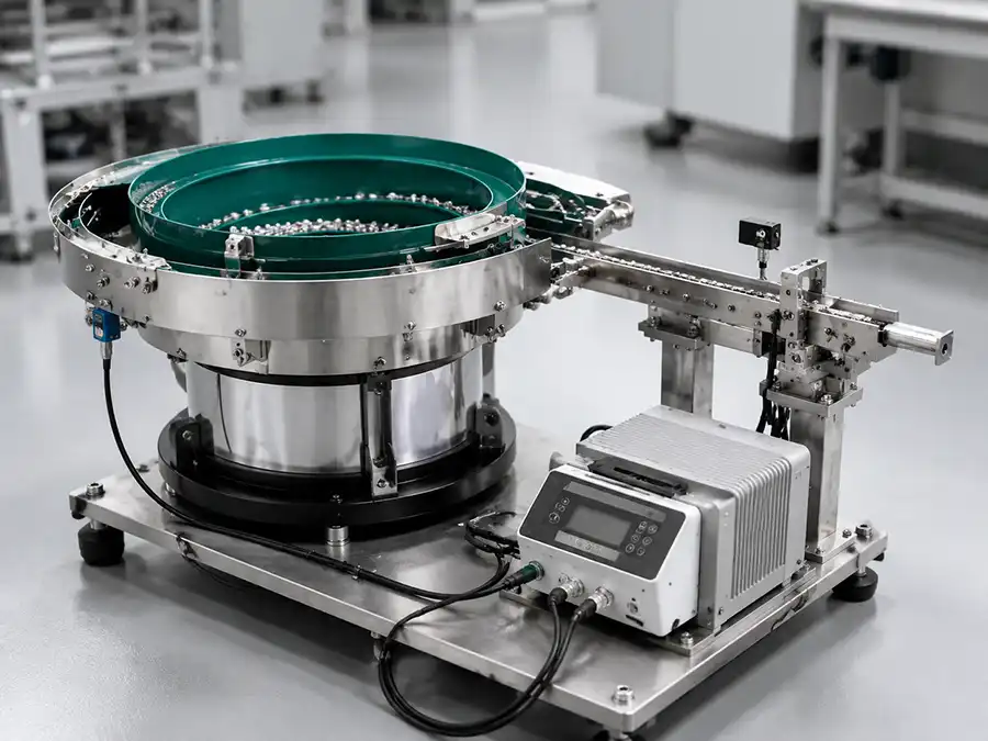
Custom vibratory bowl feeder system for precision parts
Built Around Your Actual Part Drawing review, sample testing, tooling and machine integration.
Application Review Part, orientation, rate and interface checked first
Defined Project Scope Bowl, tooling, track, controls and options documented
Agreed Acceptance Check Orientation, flow, jams and part condition reviewed
Interface Verification Outlet height, direction, sensors and signals confirmed
Direct Manufacturer Answer

What Should a Custom Vibratory Bowl Feeder Manufacturer Deliver?

A qualified vibratory bowl feeder manufacturer should deliver more than a bowl and drive. The project should define how the part will be separated and oriented, which modules are included, how the outlet connects to the next machine, and how feeding performance will be checked with representative parts before shipment.

One Engineered System, Not an Isolated Bowl

Bowl diameter alone cannot determine a workable solution. Geometry, center of gravity, surface finish, acceptable contact, required orientation, output rate and the downstream handoff all influence the tooling and configuration.

The quotation should clearly identify whether the scope includes the tooled bowl, drive, controller, hopper, linear track, level control, escapement, guarding and electrical interface. This prevents price comparisons between systems with different boundaries.

Document the required outlet orientation Use a marked drawing or photograph rather than an ambiguous text description.
Define the complete supply boundary List every included mechanical, electrical and control module.
Agree on performance checks Confirm orientation, continuous output, jams and part condition.
Verify the downstream handoff Match outlet height, direction, track geometry, sensors and signals.
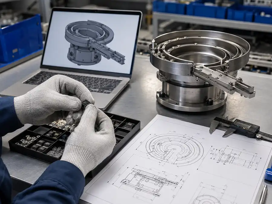
Vibratory bowl feeder customization from part drawings and samples
Drawings help define dimensions; physical samples reveal actual feeding behavior.
Drawing and Sample Customization

Custom Vibratory Bowl Feeders Built from Drawings or Samples

Custom vibratory bowl feeders can be developed from 2D drawings, 3D models, clear photographs or physical samples. Physical samples are preferred for irregular or sensitive parts because they allow engineers to test friction, center of gravity, nesting, overlapping, orientation stability and possible surface damage under actual vibration.

Samples are especially important when a component has several stable positions, a delicate finish, very small orientation differences or a tendency to become entangled with other parts.

01

Customization from Drawings

Suitable when the component dimensions and machine interface are already defined.

  • 2D drawing or 3D model
  • Dimensions, material and weight
  • Required discharge orientation
  • Target feed rate or machine UPH
  • Downstream interface drawing
02

Customization from Physical Samples

Recommended when feeding behavior cannot be confirmed from dimensions alone.

  • Evaluate center of gravity and stable positions
  • Check nesting, tangling and overlapping
  • Test sliding and surface-friction behavior
  • Verify orientation and rejection methods
  • Observe scratching or impact risks
Feasibility Before Quotation

Is a Vibratory Bowl Feeder the Right Choice for Your Part?

Vibratory bowl feeding is most effective when a part has features that can be mechanically recognized and a repeatable orientation can be maintained through the outlet. Parts should be reviewed before price or delivery is promised because geometry, surface sensitivity and product variation can change the correct feeding method.

Usually a Good Candidate

These characteristics normally support stable mechanical orientation after application testing.

  • A consistent geometry with a detectable top, bottom or direction
  • Sufficient dimensional separation between correct and incorrect positions
  • A surface that tolerates controlled sliding or a suitable protective coating
  • A production process requiring continuous, single-file component delivery
  • A defined discharge point, buffer and downstream machine cycle

Requires Special Review or Another Method

A flex feeder, tray, tube, tape or other presentation method may be safer in these conditions.

  • Bare dies, fragile optical faces or surfaces that cannot contact each other
  • Parts that are completely symmetrical but require visual feature recognition
  • Components that nest, hook, tangle or vary substantially between batches
  • Frequent product changeovers with very different shapes and dimensions
  • Cleanliness, ESD or particle limits that cannot be met by the proposed design
Engineering rule: do not approve a bowl feeder only from a keyword, catalogue photo or bowl diameter. First confirm the actual part, desired presentation, target rate, allowable contact and machine handoff.
Available Feeding Solutions

Vibratory Bowl Feeders for Semiconductor and Electronic Parts

Browse available feeder types by component and downstream application. Final compatibility should be verified using the actual part profile, required orientation and equipment interface.

Semiconductor

Semiconductor Vibratory Bowl Feeder

Precision feeding solution for semiconductor packaging, testing, sorting and automated component handling.

View feeder details
Test Handler

Test Handler Vibratory Bowl Feeder

Configured for controlled component delivery into compatible semiconductor test handlers and sorting machines.

View feeder details
IC Handling

IC Vibratory Bowl Feeder

Designed to orient compatible IC packages and deliver them into testing, inspection or sorting equipment.

View feeder details
Chip Handling

Chip Vibratory Bowl Feeder

Feeding configuration for small chip components requiring repeatable orientation and controlled transfer.

View feeder details
LED Components

LED Vibratory Bowl Feeder

Automated feeding solution for compatible LED components, lead frames and precision electronic parts.

View feeder details
SMD Components

SMD Vibratory Bowl Feeder

Precision feeding system for small surface-mount parts used in inspection, testing and assembly.

View feeder details
Manufacturer Proposal Scope

What Must Be Defined Before a Custom Bowl Feeder Is Built?

A useful proposal connects the part requirement to a specific feeding concept. It should show how incorrect orientations are rejected, what controls component accumulation, how the outlet transfers parts, and which checks determine whether the finished system is accepted.

01

Part Presentation

Record the current bulk condition and the exact required outlet orientation.

02

Orientation Logic

Define the track features, selectors, wipers or sensors used to reject wrong positions.

03

Output and Buffer

Match continuous feeder output and accumulation to the downstream machine cycle.

04

Acceptance Method

Agree on sample quantity, test duration and the observations recorded before delivery.

Production and Tooling

Vibratory Bowl Feeder Tooling, Fabrication and Integration

Reliable feeding depends on both dimensional fabrication and repeated application-specific adjustment. The tooling must be developed around the way representative components behave under vibration, not copied from a visually similar part.

Custom vibratory bowl feeder track tooling and fabrication

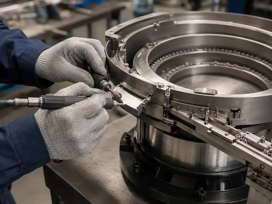
Hand-Built Bowl Tracks and Orientation Tooling

Many bowl tracks require manual forming, welding, grinding, polishing and repeated adjustment. Selectors, wipers, air jets and rejection points are tuned according to actual part behavior.

Track forming Welding Grinding Polishing Selector tuning
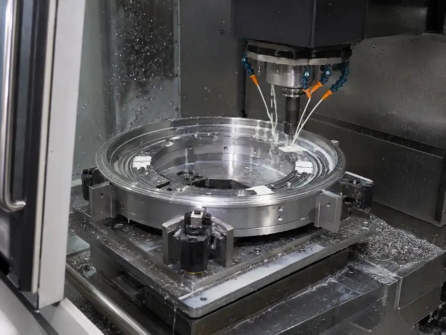
CNC machining for vibratory bowl feeder components

CNC Machining for Precision Feeder Components

CNC machining may be used for feeder bases, bowl centers, mounting parts, discharge interfaces and other components requiring controlled dimensions and repeatable installation.

Feeder bases Bowl centers Mounting parts Outlet interfaces Precision fixtures
Technical review scope for the GEEKVALUE Application Engineering Team Project recommendations should be reviewed against component geometry, requested orientation, feeding behavior and downstream equipment requirements. Final compatibility is confirmed for each project rather than assumed from a generic model name.
Controlled Project Workflow

Standardized Vibratory Bowl Feeder Manufacturing Process

Each project progresses from application review to tooling, sample testing and final configuration verification.

STEP 01

Requirement Review

Confirm component, orientation, feed rate and machine interface.

STEP 02

Drawing and Sample Analysis

Review dimensions, material, center of gravity and handling risks.

STEP 03

Feeding Concept Design

Define bowl size, orientation logic, tooling and discharge route.

STEP 04

Drawing Confirmation

Confirm outlet direction, height, footprint and connection layout.

STEP 05

Machining and Tooling

Produce components and build the track, selectors and rejection points.

STEP 06

Assembly and Tuning

Install the drive, controller, track and sensors before initial adjustment.

STEP 07

Sample Feeding Test

Verify orientation, continuous flow, rejection and part condition.

STEP 08

Inspection and Delivery

Record the final configuration, protect the system and arrange shipment.

Configuration Options

Bowl Materials, Coatings and Orientation Tooling

Material and tooling choices should be based on the component surface, feeding behavior, production environment and maintenance requirements.

Option Typical Application Primary Purpose
Stainless steel bowl Precision and industrial components Durable construction with customizable tracks and tooling.
Aluminum bowl Applications requiring lower moving mass Reduces overall bowl weight where the design permits.
PU coating Sensitive or noisy components Reduces noise, sliding impact and possible surface damage.
Soft or brush lining Parts with delicate surfaces Provides gentler contact during movement and orientation.
Mechanical wipers Parts with clear height or position differences Returns incorrectly positioned components to the bowl.
Air-jet tooling Lightweight parts or non-contact rejection Removes incorrect orientations without rigid contact.
Linear feeder track Machine buffering and controlled transfer Creates an ordered queue between the bowl and downstream equipment.
Sound enclosure Noise-sensitive production environments Reduces the operational noise reaching surrounding work areas.
Technical Selection

Key Vibratory Bowl Feeder Selection Variables

These variables affect tooling complexity, feeding stability, system price and compatibility with the production machine.

Selection Variable Why It Matters Information to Provide
Part geometry Determines how the component can be separated and oriented. Drawing, 3D model, photographs or representative samples.
Material and surface Affects friction, sliding, contamination and possible damage. Material, coating, finish and handling restrictions.
Required orientation Defines the selectors and rejection method inside the bowl. Image or drawing showing the required outlet position.
Target feed rate Influences bowl size, track layout and buffer capacity. Parts per minute, UPH and machine cycle time.
Discharge interface Controls transfer into the next machine without jamming. Outlet height, direction, track width and interface drawing.
Electrical requirements Ensures the drive and controller match the installation site. Voltage, frequency and required input/output signals.
Production environment May require special materials, coating, ESD or noise control. Cleanliness, ESD, temperature, noise and space restrictions.
Testing and Quality Control

Pre-Shipment Feeding Test and Acceptance Criteria

Before manufacturing starts, buyer and supplier should agree on the samples, required orientation, target output and test boundary. Pre-shipment inspection can then verify orientation consistency, continuous feeding, rejection behavior, jams, part condition, outlet dimensions, controller settings and interface signals.

Approved representative sample lot
Required orientation at discharge
Observed continuous feed output
Wrong-orientation rejection behavior
Bridging, doubles and jams observed
Part surface and feature condition
Outlet height, direction and track fit
Controller, sensor and signal response
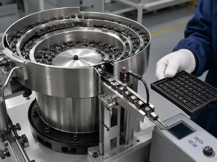
Vibratory bowl feeder sample testing and quality inspection
Testing should use representative parts and the agreed discharge orientation.
Application Engineering Scenarios

How Feeding Priorities Change by Application

These are engineering scenarios, not fixed performance claims. They show why different parts require different tooling and interface decisions. Final specifications and acceptance values must be based on the actual project.

Engineering Scenario 01

IC Package Feeding

Orientation and delivery of compatible IC packages into testing, sorting or inspection equipment.

Main concern
Package orientation
Possible tooling
Wipers and selectors
Interface
Linear track or handler inlet
Engineering Scenario 02

LED and SMD Component Feeding

Controlled handling of small electronic components with close attention to orientation and surface condition.

Main concern
Small orientation differences
Possible tooling
Track restrictions or air jets
Protection
Application-dependent coating
Engineering Scenario 03

Test Handler Integration

Bowl feeder configuration according to the handler inlet, discharge height, track direction and sensor requirements.

Main concern
Machine interface
Required data
Handler model and inlet drawing
Controls
Level and shortage signals
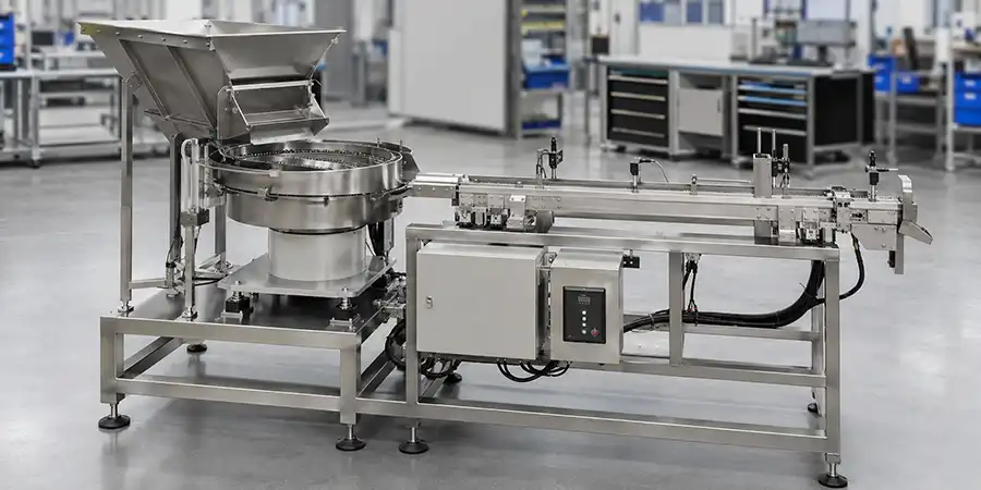
Completed custom vibratory bowl feeder with controller and linear track
A complete feeding system may combine the bowl, controller, hopper, linear track, sensors and downstream interface.
Manufacturer Evaluation

How to Evaluate Vibratory Bowl Feeder Manufacturers

Compare vibratory bowl feeder manufacturers using evidence that can be checked before order: the proposed orientation method, detailed supply scope, representative sample test, agreed acceptance criteria, interface drawing and after-sales boundary. A low equipment price alone does not show that two quotations cover the same system or that either feeder will operate reliably in production.

Part feasibility record Ask which orientation, friction, nesting and surface risks were identified.
Proposed orientation logic Ask how the track will retain correct parts and reject incorrect positions.
Representative sample test Confirm the sample source, quantity, condition and test boundary.
Written acceptance criteria Define the required orientation, output observation, jams and part condition.
Interface confirmation Verify outlet dimensions, track height, sensors, voltage and control signals.
Scope and after-sales boundary Confirm included modules, exclusions, documentation, warranty and support.
Technical RFQ Checklist

Information Required for an Accurate Bowl Feeder Quote

Bowl feeder price depends on part behavior, tooling complexity, feed rate and the modules included. Supplying complete information reduces repeated communication and improves configuration accuracy.

Send representative physical samples when possible Especially important for irregular, delicate or easily tangled parts.
Show the required outlet orientation clearly A marked photo or drawing is normally more useful than text alone.
Include downstream machine information Provide the model, inlet height, direction and available interface drawing.
Frequently Asked Questions

Vibratory Bowl Feeder Manufacturer FAQ

What is a vibratory bowl feeder?

A vibratory bowl feeder uses controlled vibration and custom tooling to separate, orient and deliver randomly loaded parts in a repeatable position for automated production equipment.

Can you customize a bowl feeder from drawings?

Yes. A feeder can be evaluated from 2D drawings, 3D models, dimensions, material, required orientation and downstream interface information. Physical samples are still recommended before final tooling is confirmed.

Why are physical part samples important?

Samples allow actual friction, center of gravity, stable positions, nesting, overlapping, orientation and surface-damage risks to be tested under vibration.

What components can a custom vibratory bowl feeder handle?

Possible applications include packaged ICs, LEDs, SMD components and other precision electronic or mechanical parts. Bare dies, fragile optical faces, completely symmetrical parts and components that tangle may require special testing or a tray, tape, tube or flexible feeding method instead.

How should I compare vibratory bowl feeder manufacturers?

Compare part-analysis capability, custom tooling experience, sample testing, feed-rate verification, quality inspection, machine-integration support and final configuration documentation.

What determines vibratory bowl feeder price?

Price is affected by part complexity, bowl size, tooling, coating, feed rate, controller, hopper, linear track, sensors, escapement and downstream integration requirements.

Can the feeder connect to a test handler or sorting machine?

Yes, when the feeder is configured for the required outlet height, direction, track width, sensor arrangement and machine-interface signals. Provide the machine model and inlet drawing before configuration.

How is a custom bowl feeder tested before delivery?

Testing should use representative parts to evaluate orientation, continuous flow, rejection behavior, jamming risk, part condition, outlet dimensions, controller settings and interface signals.

Send Your Drawings or Samples for a Feeding Evaluation

Share the part drawing, clear photos, required orientation, target feed rate and downstream equipment information. We will review the application and recommend a suitable bowl, tooling and control configuration.

Why do so many people choose to work with GeekValue?

Our brand is spreading from city to city, and countless people have asked me, "What is GeekValue?" It stems from a simple vision: to empower Chinese innovation with cutting-edge technology. This is a brand spirit of continuous improvement, hidden in our relentless pursuit of detail and the delight of exceeding expectations with every delivery. This almost obsessive craftsmanship and dedication is not only the persistence of our founders, but also the essence and warmth of our brand. We hope you will start here and give us an opportunity to create perfection. Let us work together to create the next "zero defect" miracle.

Details

Contact a sales expert

Reach out to our sales team to explore customized solutions that perfectly meet your business needs and address any questions you may have.

Sales Request

Follow Us

Stay connected with us to discover the latest innovations, exclusive offers, and insights that will elevate your business to the next level.

kfweixin

Scan to add WeChat

Request Quote