Packaged IC Devices
Orientation and transfer solutions for packaged integrated circuits entering test, inspection, sorting or packaging equipment.
Focus: orientation and package protectionave up to 70% on SMT Parts – In Stock & Ready to Ship
Get Quote →Semiconductor Component Feeding
A semiconductor vibratory bowl feeder is an automated parts-feeding system that sorts, orients and delivers IC packages, chips and discrete semiconductor devices in a controlled direction to test handlers, inspection machines, sorting equipment and packaging systems.
GEEKVALUE supplies configurable vibratory bowl feeder systems based on component dimensions, required orientation, target feed rate and machine interface. Available modules include the feeder bowl, electromagnetic drive, controller, orientation tooling, linear track, sensors and escapement.

System Overview
A semiconductor vibratory bowl feeder uses controlled vibration and customized bowl tooling to move randomly loaded IC packages into a consistent orientation. Correctly oriented components leave the bowl through a linear track and are delivered individually to a test handler, inspection system, sorting machine or packaging station.
Controlled vibration moves components around the internal bowl track. Mechanical orientation features separate incorrectly positioned parts, while correctly oriented components continue toward a linear feeder, buffer track or escapement.
Unlike a general industrial bowl feeder, a semiconductor feeding system must consider small package dimensions, delicate leads, sensitive surfaces, electrostatic control, stable orientation and accurate synchronization with downstream equipment.
The final design should therefore be based on the actual component sample, required output direction, target feed rate, available installation space and the interface of the existing machine.

Components are loaded into the feeder bowl or upstream hopper.
The drive unit moves components along the internal bowl track.
Tooling identifies and rejects incorrectly positioned components.
Correctly oriented components enter the linear feeder or buffer track.
The escapement separates components for controlled single-part release.
The component enters the handler, inspection or packaging station.
Supported Components
Component shape, weight, lead configuration and surface condition determine the required bowl tooling and track design. The following table shows common application considerations rather than fixed compatibility specifications.
Orientation and transfer solutions for packaged integrated circuits entering test, inspection, sorting or packaging equipment.
Focus: orientation and package protectionSmall and lightweight packages may require precise tooling, controlled vibration and measures that reduce overlap or incorrect orientation.
Focus: stable low-mass feedingDirection-sensitive packages and exposed leads require track clearance control and suitable rejection features.
Focus: direction and lead protectionFeeding surfaces and vibration settings can be configured to reduce unnecessary impact on optical or appearance-critical surfaces.
Focus: sensitive surface handlingComponents with leads or irregular profiles require carefully matched bowl geometry, track width and transfer clearance.
Focus: lead and profile clearanceCompact components may require anti-overlap features, fine track adjustment, suitable sensing and controlled single-part release.
Focus: precise small-part feeding| Component Type | Typical Feeding Requirement | Important Configuration Point |
|---|---|---|
| Packaged IC | Consistent direction and stable single-file transfer | Package geometry, output direction and handler interface |
| QFN / DFN | Controlled movement of small, lightweight packages | Vibration tuning, overlap prevention and surface contact |
| SOT / SOP | Direction recognition without damaging exposed leads | Track clearance, rejection tooling and transfer alignment |
| LED Packages | Stable feeding with reduced impact on sensitive surfaces | Contact material, coating and vibration amplitude |
| Transistors | Controlled movement of components with lead structures | Lead clearance, bowl tooling and linear-track geometry |
| Sensors and Chips | Precise separation and downstream presentation | Component sensing, escapement and release timing |
Final compatibility should be confirmed with component drawings, photographs and physical samples before feeder configuration.
System Configuration
A bowl feeder is only one part of the complete component-feeding process. Stable operation depends on the relationship between the bowl, drive, controller, tooling, linear track, sensors, escapement and downstream equipment.
Available Feeder Options
Review the following feeder options according to the component, downstream machine and required handling method. Final configuration should be confirmed before placing an order.
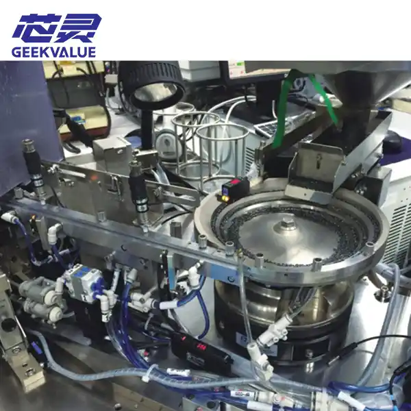
It is a precision motion control module for semiconductor test handlers.
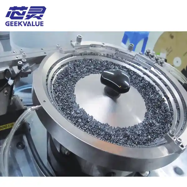
The IC bowl feeder is the core feeding module of the semiconductor test handler.
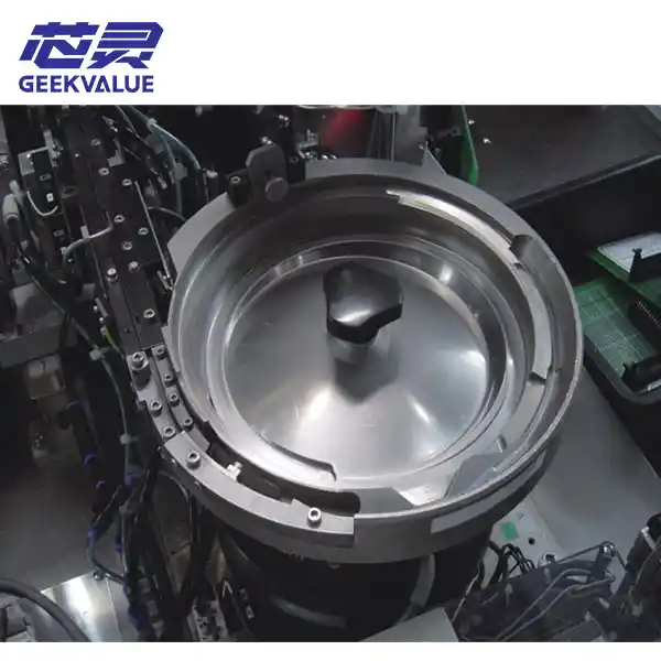
The vibratory bowl feeder for sorters is a core material-feeding module in the semiconductor packaging and testing proce...
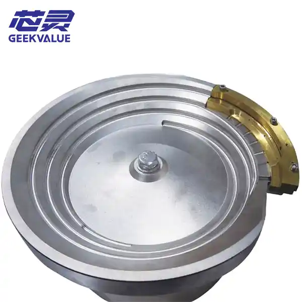
The vibratory bowl feeder is a core material feeding module in the semiconductor packaging and testing process.
Application Scenarios
The feeder outlet, buffer arrangement and release mechanism should be designed around the next process rather than treated as an independent accessory.
Supply correctly oriented packages to a handler track, pickup position, indexing mechanism or turret-based transfer system.
Maintain controlled single-file feeding before device identification, inspection, electrical testing or classification.
Present components in a consistent direction and spacing for camera inspection, measurement or appearance verification.
Deliver oriented devices toward pocket loading, tray transfer, counting, packing or other downstream packaging processes.
Selection Checklist
Selecting by bowl diameter alone is not enough. Confirm the complete feeding requirement to avoid unstable transfer, repeated jamming or incompatibility with the existing machine.
Engineering Workflow
The process begins with the component and production requirement. Each stage helps confirm whether the proposed configuration can connect with the intended machine and feeding process.
Review package data, target rate, machine model and installation conditions.
Inspect component shape, weight, contact surfaces and required direction.
Confirm bowl, tooling, drive, controller, track and sensing arrangement.
Check transfer height, mounting dimensions and downstream control signals.
Observe orientation, continuous running, separation and component condition.
Prepare export packing, documentation and remote installation communication.
Pre-Shipment Verification

Why GEEKVALUE
We help clarify component requirements, identify suitable feeder configurations and support communication between the feeding system and the existing semiconductor equipment.
Feeder configuration is discussed around the component, orientation, rate and downstream process.
Existing bowl, track, controller and installation details can be reviewed for replacement projects.
Physical components can be evaluated when tooling or feeding behavior requires confirmation.
Export packing, shipment communication and remote technical coordination are available.
Request Feeder Evaluation
The more application information you provide, the more accurately we can evaluate the bowl, tooling, track and machine-interface requirements.
Frequently Asked Questions
Send the component dimensions, required orientation, machine model and feeder photos. Our team will review the application and help identify the appropriate configuration.
Why do so many people choose to work with GeekValue?
Our brand is spreading from city to city, and countless people have asked me, "What is GeekValue?" It stems from a simple vision: to empower Chinese innovation with cutting-edge technology. This is a brand spirit of continuous improvement, hidden in our relentless pursuit of detail and the delight of exceeding expectations with every delivery. This almost obsessive craftsmanship and dedication is not only the persistence of our founders, but also the essence and warmth of our brand. We hope you will start here and give us an opportunity to create perfection. Let us work together to create the next "zero defect" miracle.
DetailsContact a sales expert
Reach out to our sales team to explore customized solutions that perfectly meet your business needs and address any questions you may have.

© All Rights Reserved. Technical Support:TiaoQingCMS
