ave up to 70% on SMT Parts – In Stock & Ready to Ship
Get Quote →ASM AD838, BESI, and K&S die bonders are selected for different semiconductor manufacturing priorities. AD838 is generally evaluated for established die attach lines where repeatable placement and operating stability are critical; BESI systems are commonly considered for advanced packaging requirements; K&S platforms are often assessed where process flexibility, existing line compatibility, or cost control matters.
The comparison below examines production stability, placement capability, process suitability, application boundaries, and practical ownership considerations for semiconductor packaging operations.
A meaningful die bonder comparison starts with the package and process requirement, not the badge on the machine frame. Die size, substrate format, attach material, placement tolerance, required output, and material handling configuration all affect whether a platform is suitable for a specific production line.
ASM AD838 is commonly evaluated for established die attach operations where repeatable placement, dependable cycle performance, and maintainable production continuity are priorities. BESI covers a broader range of die attach technologies, including systems used for multi-chip, precision flip-chip, and advanced packaging workflows. K&S should be assessed against the exact model and assembly route, because its semiconductor assembly portfolio spans different interconnect technologies rather than one direct replacement category.
Do not treat AD838, a BESI platform, and a K&S platform as automatic like-for-like alternatives. A reliable comparison should be made at model and process level after confirming the package design, die handling method, bonding material, and target production profile.
These production details determine whether a machine is technically suitable, commercially practical, and supportable after installation.
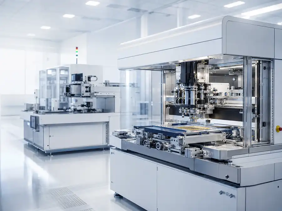
ASM AD838, BESI, and K&S equipment should not be treated as automatic like-for-like alternatives. A meaningful comparison starts with the intended die attach process, package construction, material handling method, placement requirement, and production target rather than the manufacturer name alone.
The matrix below is designed to help engineering and procurement teams identify the technical questions that should be verified before selecting a specific die bonder configuration.
Bond head design, vision options, wafer or tray handling, dispensing method, thermal process, tooling condition, and available service support can materially change whether a machine is suitable for a production line.
Use this framework to compare process fit, production integration, and ownership requirements before making a purchasing decision.
| Evaluation Area | ASM AD838 Platform | BESI Die Attach Platforms | K&S Die Attach / Advanced Packaging Platforms |
|---|---|---|---|
| Correct Comparison Level Start with the exact machine, tooling, and installed configuration. | Confirm AD838 Configuration Verify bond head type, vision package, feeder arrangement, substrate handling, and available process options. | Confirm Product Family Identify whether the proposed platform is configured for epoxy attach, soft solder, flip-chip, multi-chip, or another process route. | Confirm Assembly Route Determine whether the proposed system is intended for die attach, thermo-compression bonding, power assembly, or another application-specific process. |
| Primary Process Question Define how the die must be attached and what the finished package must achieve. | Production Die Attach Fit Review compatibility with the intended die pickup, alignment, attach sequence, adhesive or bonding material, and target output. | Process Range Fit Review whether the selected platform is matched to the required die attach technology and package development path. | Application-Specific Fit Review the process route carefully where advanced packaging, power-device assembly, clip attach, or specialized interconnect steps are involved. |
| Placement and Alignment Review Accuracy claims should always be checked under the intended production conditions. | Vision and Cycle-Time Balance Validate placement tolerance at the actual die size, substrate type, material condition, and required production cycle. | Precision by Platform Type Validate whether the selected system is optimized for high-speed die attach, high-accuracy placement, flip-chip alignment, or multi-chip handling. | Tooling and Process Dependency Validate placement capability together with bond head configuration, vision setup, tooling condition, and process-specific handling requirements. |
| Material and Package Handling Assess how dies, substrates, leadframes, strips, trays, or wafers enter and leave the system. | Line Compatibility Review Confirm supported material format, substrate dimensions, indexing method, die source, and automation interface requirements. | Package Flexibility Review Confirm whether the system configuration supports the required wafer size, substrate format, die geometry, and production material flow. | Application Tooling Review Confirm process-specific tooling, die presentation method, material transfer path, and any special inspection or interconnect requirements. |
| Production Integration Evaluate how the equipment fits the wider backend production line. | Established Line Continuity Often most relevant where an existing compatible process already depends on familiar tooling, operating procedures, and support resources. | Process Expansion Potential Often evaluated when the production roadmap includes broader die attach, flip-chip, multi-chip, or advanced packaging requirements. | Assembly Flow Compatibility Often evaluated where the die attach stage must connect with specialized assembly, interconnect, power-device, or advanced packaging operations. |
| Ownership and Support Review Purchase price alone does not describe the real operating cost of a used or refurbished die bonder. | Review Installed-Base Support Check spare-part access, software and controller condition, calibration history, available documentation, and refurbishment scope. | Review Process-Specific Support Check tooling availability, application knowledge, required consumables, process qualification needs, and service response capability. | Review Technology-Specific Support Check whether the relevant application tooling, process knowledge, spare parts, and engineering support remain available for the intended route. |
| Best Purchasing Trigger Identify the condition that makes a platform commercially and technically credible for your project. | Stable Compatible Production Need Suitable for consideration when the machine configuration closely matches an established die attach process and production continuity is the priority. | Broader Process Requirement Suitable for consideration when package development or production requirements justify a platform with the required die attach technology range. | Specific Assembly Requirement Suitable for consideration when the intended application aligns clearly with the machine’s die attach, advanced packaging, or power assembly capability. |
The strongest selection decision is usually made after confirming the package drawing, die dimensions, bonding material, target UPH, placement tolerance, automation requirement, and the actual condition of the machine being offered.
Define whether the project requires epoxy die attach, solder attach, flip-chip placement, thermo-compression bonding, or another assembly method.
Match the machine to the actual die size, substrate format, material flow, cycle target, inspection requirement, and operator workflow.
For used or refurbished equipment, confirm service records, parts condition, calibration scope, test results, available tooling, and installation support.
Engineering and procurement teams should compare die bonding equipment by the actual process route, package construction, die presentation method, bonding material, placement tolerance, target output, and serviceability of the offered configuration rather than by manufacturer name alone.
An ASM AD838 or AD838L configuration is often assessed for established die attach operations where process continuity, compatible tooling, and repeatable production performance are important. BESI platforms should be reviewed against the required die attach technology, such as epoxy attach, soft solder, multi-chip handling, flip-chip, or advanced packaging workflows. K&S equipment should be assessed according to the specific assembly route, particularly where advanced packaging, power assembly, clip attach, or legacy die attach configurations are involved.
The visual comparison highlights the areas that normally require closer technical review: production continuity, process range, advanced packaging requirements, configuration flexibility, and post-installation support readiness. Final suitability depends on the exact machine specification, tooling package, process qualification results, and condition of the offered unit.
The chart is intended to identify which evaluation areas should receive the closest review before selecting a specific ASM AD838, BESI, or K&S configuration.
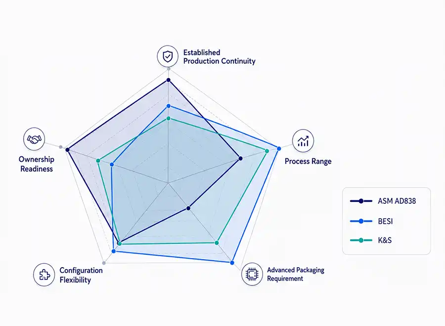
The visual map should support a structured equipment review, not replace process validation or configuration-level engineering confirmation.
Review whether the proposed configuration matches an existing die attach flow, familiar operating procedures, installed tooling, available spare parts, and known support resources.
Confirm whether the equipment can support the required attach method, die source, substrate format, bonding material, package design, and intended production route.
Determine whether the project requires higher-accuracy placement, multi-chip assembly, flip-chip alignment, thermo-compression bonding, hybrid bonding, or another advanced packaging process.
Verify bond head capability, vision options, wafer or tray handling, dispensing method, thermal process requirements, tooling availability, and automation interfaces.
For used or refurbished equipment, review calibration records, controller condition, service history, spare-part access, refurbishment scope, process tooling, and installation support.
The main engineering difference is not simply brand reputation or published placement figures. It is how a specific machine configuration performs within the intended die attach route, including die presentation, substrate handling, bonding material, vision method, tooling condition, thermal process, and production cycle requirement.
A platform may be technically capable of a process on paper but still be unsuitable if the offered configuration does not include the required bond head, wafer handling option, dispensing setup, material feeder, inspection function, or production tooling.
The most useful comparison is made after confirming the package drawing, die dimensions, attachment material, placement tolerance, target UPH, material flow, and available technical support for the exact unit under review.
An ASM AD838 or AD838L configuration is generally evaluated where the intended die attach flow can be matched to the installed material handling, bond head, vision package, substrate format, and available tooling.
The strongest fit is often found where production continuity matters: established operating procedures, compatible spare parts, known process recipes, available calibration support, and a realistic refurbishment scope for the offered unit.
BESI equipment should be reviewed at product-family level because its die attach portfolio covers different process directions, including epoxy die attach, soft solder, multi-chip assembly, flip chip, thermo-compression bonding, and hybrid bonding platforms.
The engineering question is whether the proposed platform was designed for the required package architecture and process route, rather than whether the BESI name alone represents a direct replacement for an existing die bonder.
K&S equipment should be assessed according to the specific semiconductor assembly route involved. Depending on the platform, evaluation may relate to die attach, clip attach, thermo-compression bonding, advanced packaging, power-device assembly, or a legacy installed configuration.
It is important to confirm whether the machine is intended for the same attachment process as the target production line. A system designed around a specialised interconnect or power assembly route should not automatically be compared with a conventional die attach configuration.
Semiconductor packaging applications should be segmented by the attachment process and package construction rather than by a general brand label. The same product family may be configured differently for epoxy attach, solder attach, flip-chip placement, multi-chip assembly, power-device packaging, or specialised interconnect processes.
A machine should only be considered suitable after its handling method, tooling, bonding approach, placement capability, material flow, and support condition are confirmed against the intended production program.
Suitable where the process uses a proven die attach sequence and the priority is maintaining stable output with compatible die handling, substrate handling, adhesive or solder process control, and repeatable operating procedures.
An AD838 configuration may be relevant when its installed options closely match the existing production route and the available tooling can support the required package format.
Power-device assembly often requires close review of die size, bond material, thermal requirements, leadframe or substrate format, and the mechanical behaviour of the final package.
Systems designed for soft solder, conductive adhesive, clip attach, or other power-package processes should be compared against the exact package and thermal path requirement.
These applications require more than basic die placement. Evaluation may include die orientation, bump or interconnect structure, alignment accuracy under production conditions, substrate warpage, flux or adhesive handling, and inspection requirements.
BESI and K&S product families may include platforms relevant to such routes, but the exact system configuration must be verified before comparison.
Applications involving thermo-compression bonding, hybrid bonding, high-density interconnects, stacked die, or complex multi-die modules require a dedicated process review rather than a direct comparison with a conventional die bonder.
The decision should consider the full process window, thermal profile, bonding force range, material preparation, metrology, yield target, and engineering support plan.
The right die bonder is the machine that can complete the intended process consistently within the required production window, while remaining supportable after installation. Brand comparison is useful only after the technical route has been defined.
Confirm whether the project requires epoxy attach, eutectic or soft-solder attach, conductive adhesive, flip-chip placement, thermo-compression bonding, clip attach, or another specialised assembly method.
Verify die dimensions, die thickness, wafer or tray presentation, substrate or leadframe format, strip indexing, material transfer path, and the need for dispensing, heating, curing, or inspection.
Review the actual bond head, vision package, handling modules, tooling, thermal process, automation interface, software condition, and available options on the offered system.
Compare the expected output, changeover demand, maintenance needs, spare-part access, calibration scope, service coverage, qualification workload, and total cost of ownership.
Consider an ASM AD838 configuration when it closely matches an established die attach process and production continuity is the priority. Consider a BESI platform when the required package and attach route align with the specific technology family under review. Consider a K&S platform when the exact equipment configuration supports the intended die attach, advanced packaging, clip attach, thermo-compression, or related assembly process.
A technically capable machine can still become an unsuitable purchase when the offered configuration, process tooling, machine condition, or available support does not match the target production requirement.
Placement figures, cycle-time claims, and supported package lists should be reviewed under the actual die size, material condition, substrate type, process window, and production target required by the project.
Two machines from different manufacturers may serve different assembly routes even when both are described as die bonding equipment. Direct replacement should only be considered after process and configuration verification.
For used or refurbished equipment, the condition of controllers, mechanics, vision modules, feeders, bond heads, safety systems, calibration records, and available spare parts can be as important as the original platform design.
Before shipment, confirm available tooling, sample materials, test procedure, acceptance criteria, installation requirement, electrical and utility needs, and the scope of technical support after commissioning.
The following questions address the practical issues that usually need clarification before comparing specific semiconductor die bonding configurations.
Only when the exact machines are intended for the same attach process and package type. The comparison should include die size, substrate format, bonding material, handling method, placement requirement, automation level, tooling, and the condition of the offered unit.
No. Suitability depends on the installed configuration, including bond head, material handling, substrate format, vision setup, tooling, process option, and the requirements of the intended production line.
Confirm the exact configuration, supported material format, die source, bond head condition, vision system, automation modules, available tooling, calibration status, spare-part access, and refurbishment scope.
No. BESI has different equipment families for different die attach and packaging routes. The specific platform should be matched to the required process, such as epoxy attach, soft solder, flip chip, multi-chip assembly, thermo-compression, or hybrid bonding.
Confirm the intended assembly route and machine configuration. Depending on the platform, the relevant process may involve die attach, clip attach, thermo-compression bonding, power-device assembly, advanced packaging, or a legacy installed process.
Neither should be evaluated alone. The required placement tolerance must be achieved consistently at the intended cycle time, die condition, substrate condition, bonding material, and production output level.
The biggest risk is process mismatch combined with incomplete support readiness. A machine may appear suitable until missing tooling, unsupported software, worn mechanical components, unavailable spare parts, or incomplete calibration records affect installation and qualification.
Provide the package drawing, die dimensions, die thickness, attach material, substrate or leadframe format, target UPH, placement tolerance, available utilities, automation requirement, and any existing tooling or process constraints.
Why do so many people choose to work with GeekValue?
Our brand is spreading from city to city, and countless people have asked me, "What is GeekValue?" It stems from a simple vision: to empower Chinese innovation with cutting-edge technology. This is a brand spirit of continuous improvement, hidden in our relentless pursuit of detail and the delight of exceeding expectations with every delivery. This almost obsessive craftsmanship and dedication is not only the persistence of our founders, but also the essence and warmth of our brand. We hope you will start here and give us an opportunity to create perfection. Let us work together to create the next "zero defect" miracle.
DetailsContact a sales expert
Reach out to our sales team to explore customized solutions that perfectly meet your business needs and address any questions you may have.

© All Rights Reserved. Technical Support:TiaoQingCMS
