
 EN
EN id
id sk
sk sr
sr sv
sv it
it pt
pt bn
bn ms
ms be
be nl
nl fr
fr th
th vi
vi ru
ru ja
ja ko
ko de
de hy
hy az
az bs
bs bg
bg my
my cs
cs da
da dv
dv el
el et
et fil
fil fi
fi ga
ga gl
gl gn
gn he
he hi
hi km
km hr
hr hu
hu is
is kn
kn rw
rw lo
lo lv
lv lt
lt lb
lb lg
lg mi
mi mt
mt ne
ne no
no ny
ny or
or om
om per
per pl
pl ro
ro sa
sa so
so es
es sw
sw ta
ta tr
tr uk
uk ur
ur cy
cy xh
xh
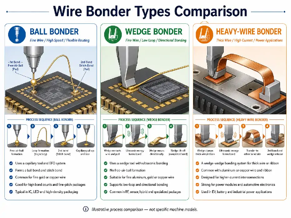
Choosing a wire bonding machine begins with the interconnect that the product needs, not with a preferred machine brand. Ball bonders, fine-wire wedge bonders and heavy-wire bonders use different tools, wire-control systems and process conditions, even when all three are described broadly as wire bonding equipment.
The distinction is also more precise than the three labels may suggest. Heavy-wire bonding is generally a wedge-wedge bonding application designed around larger aluminum or copper wire, ribbon and higher-current interconnections. It should not be treated as a completely separate bonding principle from wedge bonding.
For a general explanation of wire bonding equipment and basic process steps, review the wire bonder technology guide. This article focuses on selecting the correct equipment direction for a defined package and production requirement.
Start with the Interconnect Requirement
A machine category cannot be selected reliably from the package name alone. Two products described as power devices, sensors or semiconductor modules may require very different wire materials, bond geometries and production systems.
| Selection Input | What to Define | Why It Changes the Machine Direction |
|---|---|---|
| Electrical requirement | Signal, current, voltage, frequency and allowable electrical loss | It affects wire cross-section, ribbon use, number of parallel wires and bond area. |
| Wire or ribbon | Gold, copper or aluminum; round wire or ribbon; required dimensions | The material and cross-section determine the bond head, tool, wire path and ultrasonic system. |
| Bond-pad surfaces | Die metallization, substrate finish, leadframe plating and surface condition | The complete material interface affects bond formation and the usable process window. |
| Package geometry | Pad pitch, access depth, bond direction, package size and surrounding obstructions | Some layouts favor the directional control and low loops of wedge bonding, while others favor ball-bonding flexibility and speed. |
| Loop requirement | Loop height, span, clearance, direction and resistance to wire movement | The loop profile may determine whether a capillary, fine-wire wedge or heavy-wire tool is practical. |
| Thermal limit | Workholder temperature, material sensitivity and allowable package heating | Ball bonding commonly uses a thermosonic process, while ultrasonic wedge processes may support lower-temperature applications. |
| Mechanical requirement | Vibration, thermal cycling, pull strength, shear behavior and environmental exposure | Power, automotive and harsh-environment products may require a more robust wire or ribbon interconnect. |
| Production model | Volume, product mix, changeovers, loading method and traceability needs | A laboratory wedge bonder and an automated heavy-wire production system solve different manufacturing tasks. |
These requirements should be defined before individual models are compared. A machine that supports the correct wire material may still be unsuitable because of its bonding area, workholder, automation, loop capability or software configuration.
Ball Bonders Prioritize Fine-Wire Productivity and Flexibility
Ball bonding normally forms a free-air ball at the end of a fine wire using an electronic flame-off system. A ceramic capillary places the ball onto the first bond location, forms the wire loop and completes the connection with a stitch bond at the second location.
Modern ball bonding is commonly associated with fine gold and copper wire, high-density semiconductor packaging and automated production. Depending on the machine and package process, applications can include:
Logic, memory and analog integrated circuits
Discrete semiconductor devices
LED and optoelectronic packages
Stacked-die and multi-chip packages
System-in-package and high-density interconnect designs
High-volume leadframe and substrate-based assembly
Reasons to Evaluate a Ball Bonder
High production output is important.
The package uses fine gold or copper wire.
The bond layout requires wires to fan out in many directions.
The product has a large number of bonds per device.
Fine-pitch and high-density package assembly are required.
Automated material handling and high-volume recipe control are priorities.
The capillary provides substantial directional flexibility because the round tool can form loops toward different second-bond locations without requiring the bond itself to follow a wedge orientation.
Conditions That Still Require Verification
The presence of a ball-bond head does not prove compatibility with every fine-wire package. Machine selection must still consider:
Supported wire material and diameter
EFO system and free-air-ball stability
Capillary geometry and tool clearance
Pad pitch and bond placement requirement
Loop height, span and stacked-die geometry
Workholder temperature and package support
Copper-wire capability and protective-gas requirements where applicable
Handler, leadframe or substrate format
A high-speed ball bonder may therefore be the correct machine category but still require a different bond head, workholder, capillary or software option for the intended package.
Fine-Wire Wedge Bonders Support Low Loops and Directional Bonding
Wedge bonding uses a wedge-shaped tool to press the wire against the bond surface while ultrasonic energy and force create the interconnection. The process normally creates wedge bonds at both ends of the wire and does not require free-air-ball formation.
Fine-wire wedge bonding can use aluminum, gold or copper wire, depending on the machine, tool and process. It is often evaluated where package geometry, thermal limits or interconnect shape make wedge bonding more suitable than a conventional ball-bonding route.
Reasons to Evaluate a Fine-Wire Wedge Bonder
The package requires very low or short loops.
Vertical clearance above the package is limited.
The application uses fine aluminum wire.
Low-temperature ultrasonic bonding is preferred.
The bond geometry requires elongated wedge bonds.
Ribbon is needed for an RF or high-frequency interconnect.
The product is a hybrid circuit, sensor, MEMS device, RF module or specialized microelectronic assembly.
The directional nature of a wedge tool is an important design factor. The tool, bond head or workpiece must be oriented according to the wire path. This can provide strong control over bond direction and low-profile geometry, but it may also affect cycle time and machine architecture.
Fine Pitch Does Not Automatically Mean Wedge Bonding
Both modern ball and wedge bonders can support fine-pitch applications under appropriate conditions. The correct choice depends on the complete geometry.
Ball bonding may remain preferable when high output and multi-directional fan-out are more important. Wedge bonding may become more attractive when low loop height, narrow elongated bonds, deep access, wire material or ribbon orientation controls the design.
Heavy-Wire Bonders Serve Power and High-Current Interconnections
A heavy-wire bonder is generally an ultrasonic wedge-wedge system configured for larger wire or ribbon. The bond head, transducer, wire guides, clamps, cutter and workholder are designed for substantially different mechanical loads than a fine-wire system.
Typical material directions include aluminum or copper round wire and aluminum or copper ribbon. The actual supported range depends on the bond head and machine configuration.
Typical Heavy-Wire Applications
Power semiconductor modules
IGBT and SiC device assembly
Automotive traction inverters
DC/DC converters and industrial power electronics
Battery-module and cell interconnections
High-current discrete devices
Power hybrid circuits
Large-area copper or aluminum interconnections
Reasons to Evaluate a Heavy-Wire Bonder
The interconnect must carry higher current than a conventional fine wire.
The design requires thick aluminum or copper wire.
Ribbon is needed to increase interconnect area or support a specific electrical design.
The package has a large bonding area or power-module format.
The process requires multiple parallel wires or ribbons.
Mechanical durability under thermal and vibration stress is important.
The production line needs automated module, leadframe or battery handling.
Heavy-wire equipment should not be selected only from the current rating of the final device. The machine must also match the pad size, surface material, wire deformation, ultrasonic power, workholder support, package stiffness and required bond-test method.
Compare the Three Equipment Directions
| Selection Area | Ball Bonder | Fine-Wire Wedge Bonder | Heavy-Wire or Ribbon Bonder |
|---|---|---|---|
| Basic bond process | Ball bond followed by a stitch bond | Fine-wire wedge-wedge bonding | Heavy-wire or ribbon wedge-wedge bonding |
| Primary tool | Ceramic capillary | Fine-wire wedge | Heavy-wire or ribbon wedge |
| Ball formation | Requires EFO and free-air-ball formation | Not required | Not required |
| Common material direction | Fine gold or copper wire | Fine aluminum, gold or copper wire; selected ribbon applications | Heavy aluminum or copper wire and ribbon |
| Typical strength | High-speed, flexible fine-wire package assembly | Low-profile, directional and specialized interconnections | High-current and power-device interconnections |
| Loop behavior | Flexible fan-out and complex programmed loops | Low and short loops with directional tool control | Controlled larger-wire loops, parallel wires or ribbon paths |
| Thermal direction | Commonly thermosonic with a heated workholder | May use ultrasonic room-temperature bonding or thermosonic conditions | Commonly ultrasonic, with process conditions defined by material and application |
| Typical production use | IC, LED, discrete and high-density package production | RF, hybrid, sensor, MEMS and specialized microelectronics | Power modules, automotive power, batteries and industrial electronics |
| Important machine checks | EFO, capillary, wire feed, looping, heater and high-speed handler | Theta control, wedge tool, clamp, cutter, loop direction and package access | Bond-head power, transducer, thick-wire feed, cutter, workholder and large-area automation |
This table identifies the likely equipment direction. It does not replace an application review, because individual machines within the same category can have very different bonding areas, wire ranges, automation and quality-monitoring functions.
Wire Material Alone Cannot Select the Machine
Statements such as “we use copper wire” or “the product requires aluminum wire” are not sufficient for machine selection.
Copper may appear in fine-wire ball bonding, fine-wire wedge bonding or heavy-wire power applications. Aluminum is strongly associated with wedge bonding, but its required diameter and package geometry determine whether the project needs a fine-wire system or a heavy-wire production platform.
For every proposed wire or ribbon, confirm:
Material and alloy
Diameter or ribbon width and thickness
Spool type and feeding arrangement
Required tool geometry
Bond-pad and terminal material
Ultrasonic frequency and process-energy range
Loop or ribbon-path geometry
Expected pull, shear or peel behavior
A machine listing that mentions the correct metal but does not identify the supported dimensions, bond head and tooling is incomplete for selection purposes.
Package Geometry Can Override the General Application Rule
Typical application labels are useful but not absolute. A power-related product does not automatically require a heavy-wire bonder, and an IC package does not automatically require ball bonding.
Evaluate the physical design:
Can the bonding tool reach every pad without contacting nearby structures?
Does the wire need to fan out in many directions?
Is the available vertical clearance sufficient for the intended loop?
Does the bond need an elongated wedge shape?
Is ribbon orientation important to the electrical design?
Can the workholder support the package during ultrasonic bonding?
Is the bonding area within the machine’s motion range?
Does the product require one wire per connection or several parallel wires?
The answer may change the selected process even when the material and product category initially point in another direction.
Production Requirements Determine the Machine Configuration
After the bonding process has been selected, compare how the machine will operate in production.
| Production Factor | Configuration Questions |
|---|---|
| Loading method | Will packages be loaded manually, by magazine, leadframe handler, reel system, tray or custom automation? |
| Bonding area | Can the machine reach the complete device, module, panel or battery assembly? |
| Product changeover | Which workholders, tools, wire paths and recipes must change between products? |
| Output | How many devices and bonds are required per hour under the real package sequence? |
| Quality monitoring | Are process monitoring, bond-process control, pull testing or traceability functions required? |
| Recipe control | How will bond parameters, loop programs, images and product data be stored and recovered? |
| Factory integration | Are host communication, barcode, MES or production-data interfaces required? |
| Future products | Does the machine need additional wire sizes, larger working areas or alternative bond heads? |
A development laboratory may prioritize manual access, process flexibility and interchangeable bond heads. A mass-production IC line may prioritize ball-bonding speed and automated handling. A power-module or battery line may require a large work area, heavy-wire head, strong fixture and product-specific automation.
A Practical Wire Bonder Selection Sequence
Define the electrical connection. Establish current, frequency, resistance and reliability requirements.
Select the wire or ribbon direction. Identify the material, cross-section and number of interconnects.
Review the bond surfaces. Confirm the die pad, terminal, leadframe or substrate metallization.
Map the package geometry. Record pad pitch, tool access, loop height, bond direction and working area.
Confirm the thermal budget. Determine whether the package can support the required heated or low-temperature process.
Choose the bonding process. Compare ball bonding, fine-wire wedge bonding and heavy-wire wedge bonding against the defined interconnect.
Choose the machine configuration. Review bond head, wire path, tool, workholder, vision, handler and software.
Test representative materials. Demonstrate the intended bond sequence, loop and measurable bond result.
Review production fit. Confirm output, changeover, automation, data and support requirements.
Inspect the exact machine. For used equipment, connect the installed configuration and test evidence to the machine serial number.
This sequence reduces the risk of selecting a familiar brand or machine model before the actual bonding requirement has been defined.
When More Than One Bonder Type May Be Needed
Some products contain more than one interconnect requirement. A package family may use fine-wire ball bonding for signal connections while a related power product uses heavy aluminum wire or ribbon.
A single machine should not be assumed to cover both directions unless it has a verified interchangeable bond-head architecture and the required wire-feed, tooling, workholder and software support. Even then, changeover time, calibration and production volume may make separate machines more practical.
Mixed product portfolios should therefore be reviewed by process family rather than selecting one universal wire bonder for every package.
Ball, Wedge and Heavy-Wire Bonder FAQ
Is a heavy-wire bonder different from a wedge bonder?
A heavy-wire bonder is normally a specialized wedge-wedge bonding system. It uses a bond head, transducer, wire path and cutter designed for larger wire or ribbon and is commonly applied to power and high-current products.
Is ball bonding always faster than wedge bonding?
Ball bonding is generally favored for high-speed fine-wire production, but actual output depends on the package, number of bonds, loop program, machine automation and inspection requirements. Published maximum speed should not replace a product-specific cycle review.
Can a wedge bonder use gold wire?
Yes, applicable wedge systems can use gold wire, but the bonding mode, temperature, wedge tool and machine configuration must match the selected wire and bond surfaces.
Should power semiconductor products always use heavy wire?
No. The correct interconnect depends on current, package design, pad size, thermal behavior and reliability requirements. Some power-related devices may use fine wire, ribbon, clips or another interconnect technology.
Can one machine bond both fine wire and heavy wire?
Some flexible or development systems offer interchangeable bond heads, but this capability must be verified on the exact machine. A fine-wire head cannot be assumed to process heavy wire simply because both use wedge bonding.
Final Recommendation
Select the bonding process before selecting the machine model. Ball bonders are generally the strongest direction for high-speed fine-wire semiconductor packaging. Fine-wire wedge bonders become important where low loops, directional bonds, low-temperature processing or specialized materials control the design. Heavy-wire and ribbon bonders serve power, automotive, battery and high-current applications that require a larger interconnect and a more powerful wedge-bonding system.
After identifying the correct process direction, compare available wire bonding equipment by its exact bond head, wire range, tooling, workholder, automation and test capability. To discuss a package or an identified machine, send the wire or ribbon specification, package drawing, pad materials, loop requirement and production target through the All-SMT contact page.
