EN
EN id
id sk
sk sr
sr sv
sv it
it pt
pt bn
bn ms
ms be
be nl
nl fr
fr th
th vi
vi ru
ru ja
ja ko
ko de
de hy
hy az
az bs
bs bg
bg my
my cs
cs da
da dv
dv el
el et
et fil
fil fi
fi ga
ga gl
gl gn
gn he
he hi
hi km
km hr
hr hu
hu is
is kn
kn rw
rw lo
lo lv
lv lt
lt lb
lb lg
lg mi
mi mt
mt ne
ne no
no ny
ny or
or om
om per
per pl
pl ro
ro sa
sa so
so es
es sw
sw ta
ta tr
tr uk
uk ur
ur cy
cy xh
xh
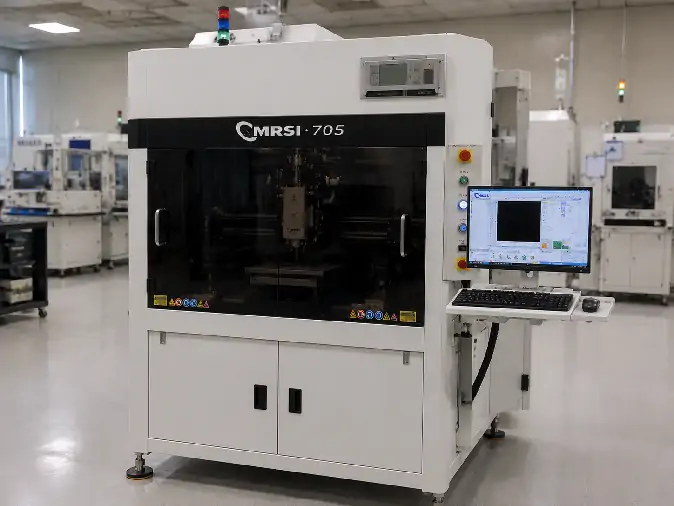
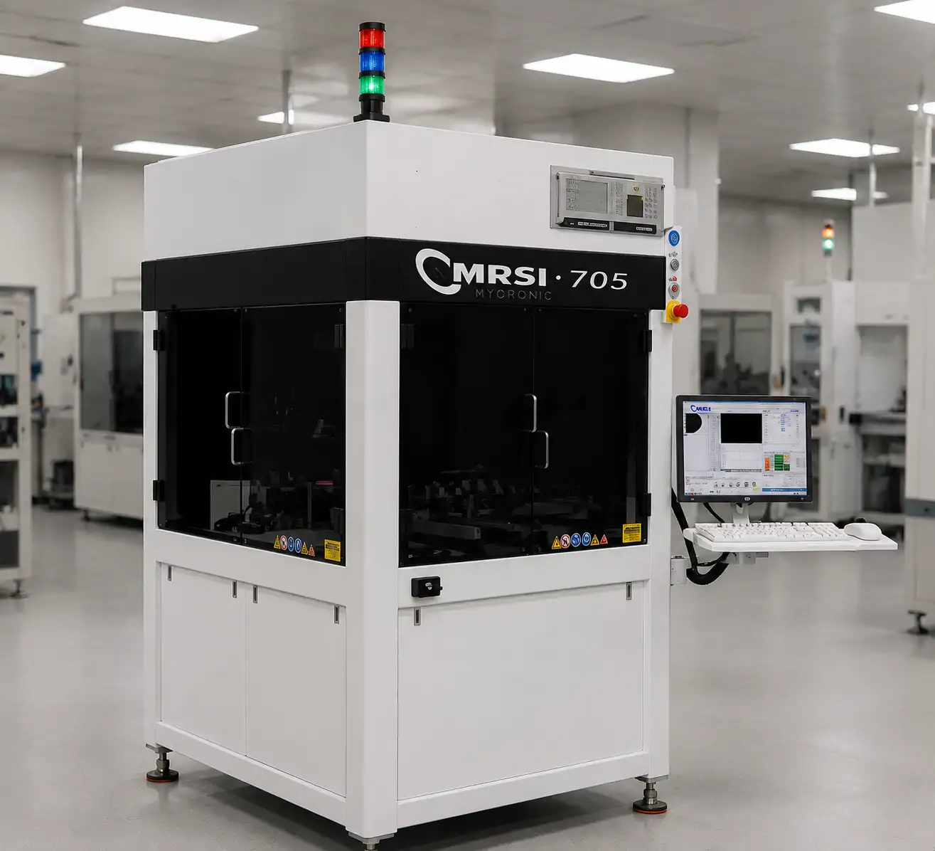
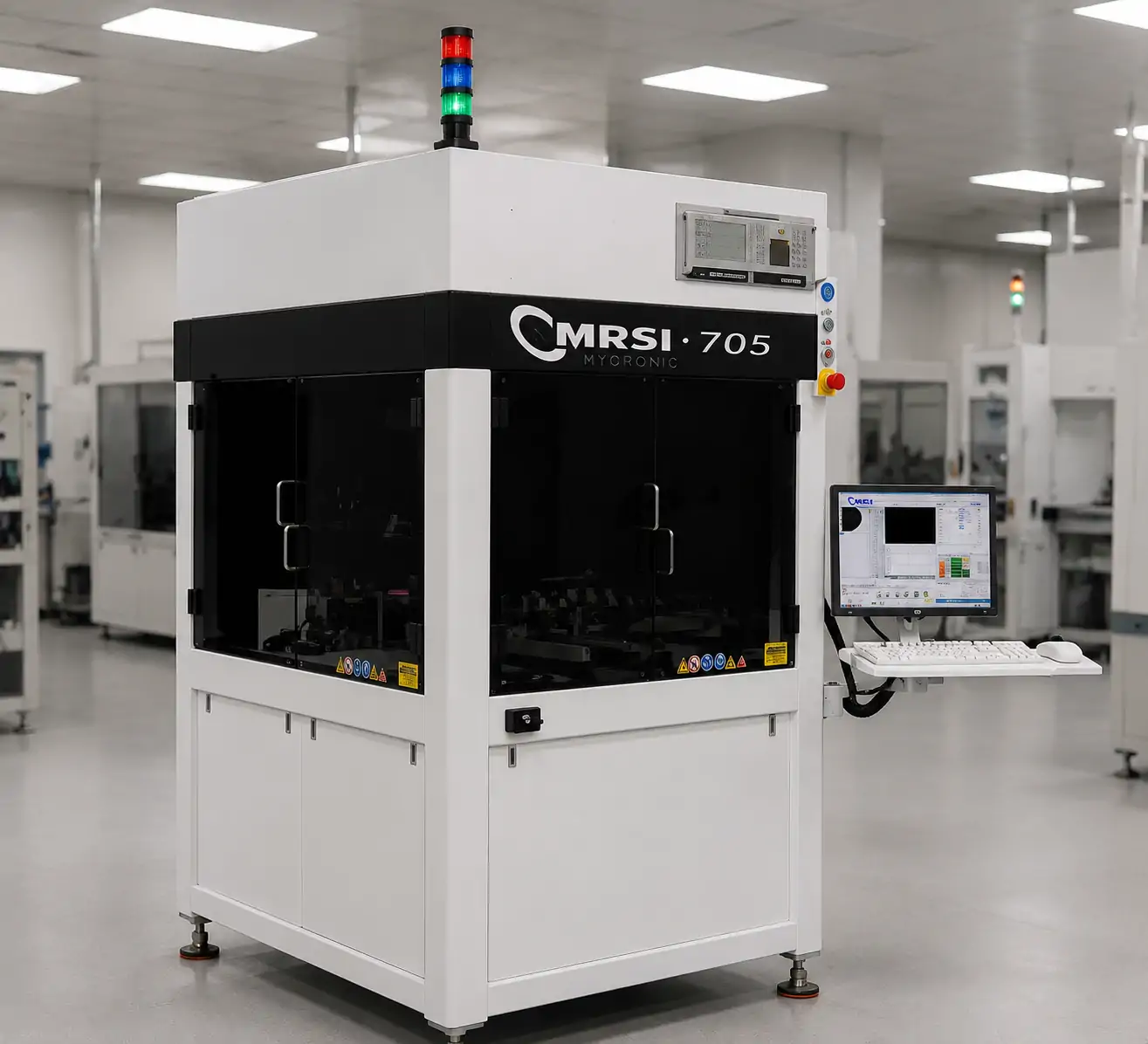
The MRSI-705 is a configurable high-precision die-bonding and component-assembly platform officially positioned as a 5-micron die bonder. Its precision comes from the interaction of mechanical stability, controlled motion, position feedback, force control, machine vision, tooling and process software rather than from one isolated specification.
The 5-micron designation refers to the platform’s placement-accuracy positioning. It does not describe die size, and it should not be confused with the finer resolution of the machine’s position encoders. Actual project results still depend on the component, substrate, tooling, calibration, material behavior and installed process modules.
This article explains the common MRSI-705 platform foundation and its main assembly directions before project-specific configuration selection begins.
What the MRSI-705 Is
Mycronic identifies the MRSI-705 as a flexible, configurable 5-micron die bonder for high-precision component assembly. It provides a controlled platform for picking components, identifying their orientation, aligning them with a substrate or target and completing the required placement or bonding sequence.
The machine is relevant to die attach, flip-chip assembly and other processes where component handling, alignment, tooling and bonding conditions require close control.
Its configurable design allows material inputs, tools, bonding technologies and production strategies to be selected around the intended assembly. The model name identifies the precision platform, but it does not reveal every module installed on a particular machine.
What “5-Micron Die Bonder” Means
Official information states placement accuracy of ±5 microns or better for the MRSI-705 platform. This describes its placement-accuracy category under the relevant machine and process conditions.
| Term | What It Describes | What It Does Not Prove |
|---|---|---|
| 5-micron platform | Official placement-accuracy positioning of ±5 microns or better | Guaranteed accuracy for every product, tool or bonding process |
| 0.1-micron encoder resolution | The scale used for fine axis-position feedback | Final component placement accuracy of 0.1 micron |
| Actual process result | The outcome produced by the complete configured process | A result determined by the model name alone |
Encoder resolution describes how finely the control system can measure or report axis position. Placement accuracy reflects a larger system that includes structural stability, axis behavior, vision alignment, tooling, calibration, component features and material movement.
A meaningful project assessment therefore combines the official platform specification with the real process environment. Tool stiffness, substrate stability, thermal effects, image quality and the selected bonding sequence can all influence the final result.
Mechanical Architecture for Stable, Controlled Motion
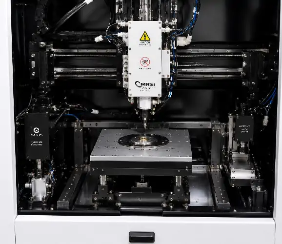
The MRSI-705 uses a solid granite-supported overhead structure. Granite provides a stable mechanical reference, while the overhead arrangement supports controlled movement above the bonding work area.
Actively cooled ironless linear motors drive the motion system. They provide direct axis movement without a conventional mechanical transmission, while active cooling helps manage thermal change during operation.
High-resolution linear encoders return position information to the control system. Official information states that the encoder scales offer 0.1-micron resolution. The Z axis uses air-bearing technology to support smooth vertical movement with reduced mechanical contact.
The relationship can be understood as:
Stable structure → Controlled motion → Fine position feedback → Repeatable pickup, alignment and placement
The benefit comes from the granite structure, motors, encoders, vertical-axis design, tooling and control software working together. No single element independently guarantees the final placement result.
Force Control for Fragile and Process-Sensitive Components
The MRSI-705 includes closed-loop force feedback. Rather than relying only on a commanded bonding-head position, the control system can monitor force during contact and regulate the process according to the programmed requirement.
Official information states that component force can be programmed as low as 10 grams. This may be useful for thin, fragile or force-sensitive parts that could be damaged by excessive contact.
The correct force still depends on the component, bonding material, joint-formation method and tooling. A suitable tool must support the intended contact area without damaging the part or introducing unwanted movement.
Machine Vision, Orientation Detection and Alignment
Machine vision helps identify the component before pickup and establish its orientation. Official platform information includes vision-based die detection and 360-degree orientation recognition, allowing the system to respond when components are presented at different rotational positions.
Substrate-fiducial alignment provides a physical reference for placing the component relative to the target. Instead of relying only on a stored machine coordinate, the system can locate actual features on the substrate and use them during alignment.
Programmable lighting supports recognition across different surfaces, markings, edges and fiducial styles. The most effective lighting and vision recipe can therefore vary from one product to another.
Vision quality is influenced by optics, feature contrast, calibration, tooling stability and the relationship between measured features and the final bonding point. It cannot compensate by itself for an unstable substrate, unsuitable tool or poorly defined alignment reference.
Material Input and Tooling Support High-Mix Assembly
Depending on the installed configuration, the MRSI-705 platform may receive components through wafer formats, waffle packs, Gel-Paks, tape feeders or other application-specific presentation methods.
The selected format affects how components are located, picked and oriented, which tools are required and how efficiently the system can move between products. A wafer-based process may need die-position data and dedicated wafer handling, while waffle packs, Gel-Paks and tape-fed materials introduce different presentation and changeover requirements.
Pickup and placement tools are also application-specific. Their contact surfaces, dimensions and materials must suit the component, while bonding tools may need to support heat, force or other process conditions.
Platform flexibility allows the machine to be configured around different material strategies, but the required input device, tool and conversion hardware must still be identified for the actual assembly.
Assembly Technologies Associated With the MRSI-705
Eutectic Bonding
Eutectic bonding uses a controlled material and thermal process to form the joint between the component and target. The process may involve dedicated heating, tooling and control functions selected for the material system.
Epoxy Die Attach
Epoxy die attach uses an adhesive material system to secure the component to its target. Material may be applied through dispensing or another controlled method before placement, with curing handled according to the selected adhesive process.
In-Situ UV Bonding
In-situ UV bonding combines a UV-curable material with compatible exposure hardware. The sequence must preserve alignment while the material is applied, positioned and cured.
Flip-Chip Assembly
Flip-chip assembly places the active or interconnect side of the die toward the mating surface. This changes the pickup, orientation, alignment, support and bonding-tool requirements.
Thermal-Compression Bonding
Thermal-compression bonding combines controlled heat and force to form the connection. Tool design, temperature control, material behavior and process timing all contribute to the result.
These are platform technology directions rather than a list of functions installed on every MRSI-705. Each process requires the corresponding hardware, software, tooling and qualified sequence.
Core Platform Capability and Installed Configuration
The MRSI-705 provides a common precision foundation: a stable structure, controlled motion, fine position feedback, closed-loop force control and machine vision. These capabilities support several assembly directions, but they do not create one universal machine configuration.
Flip-chip assembly may need dedicated orientation hardware and process tools. Eutectic bonding may require a heated head or work area. Epoxy assembly can require dispensing equipment, while an in-situ UV process needs compatible curing hardware. Thermal-compression bonding introduces its own force, temperature and tooling requirements.
Material-input equipment must also match the project. A machine prepared for waffle packs may not contain the modules required for wafer or tape input. Software, licenses and recipes connect the installed hardware to the intended assembly sequence.
The platform describes what can be engineered around the MRSI-705, while the installed configuration determines what an individual machine can perform.
The MRSI-705 and MRSI-705HF should also remain separate technical identities. High-force or extended-heating information associated with the HF version must not be transferred to the standard MRSI-705 without model-specific evidence.
Optional Tooling and Production Strategy
Mycronic describes an optional higher-volume turret that can hold up to 12 tools. By keeping several tools available within one configured system, it can reduce separate tool-change steps in assemblies that use multiple sequential tools.
The turret may support higher product variety, more complex assembly sequences or production routes that would otherwise require repeated tool changes. It is not standard on every MRSI-705 and does not establish one universal throughput figure.
The configurable work area also makes the platform relevant to research, process development and new-product introduction. Engineers can adapt material presentation, tooling, vision recipes and bonding steps as the assembly matures.
With an appropriate configuration, the MRSI-705 may support low- to medium-volume production and, in selected cases, higher-volume strategies. Suitability depends on the product mix, material presentation, number of process steps, tool changes, inspection requirements and target cycle.
Representative Application Areas
Official material associates the MRSI-705 with microwave modules, photonics packaging, RF power amplifiers, infrared and pressure sensors, MEMS, semiconductor packaging, hybrid electronics, multichip modules and laser-diode bonding.
These applications may benefit from precise placement, orientation control, fragile-component handling and flexible bonding technologies. Photonics and laser-diode assemblies can involve demanding alignment and controlled contact, while hybrid and multichip modules may combine several component types and process steps.
An application label establishes possible relevance rather than compatibility with a specific product. The actual die, substrate, alignment references, bonding method, material system and tooling determine whether the platform can be configured for the project.
Move From Platform Research to Configuration Review
A project-specific review becomes useful once the component, substrate and bonding objective are defined. The starting information should include component dimensions and material, target substrate, required placement accuracy, orientation, bonding method and bonding material.
Force or heating needs, input format, tooling, inspection or curing requirements, product mix and expected production volume also influence the configuration. Together, these factors determine which material-handling equipment, vision setup, process modules and production tools should be considered.
The next step is an MRSI-705 configuration review based on the real assembly. Contact the technical team by email or WhatsApp to discuss the project. Component drawings, substrate information, tooling photographs and process documents can be attached after the conversation is opened.
Compatibility, installed options, process performance, price and delivery should be discussed only after the project requirements and relevant machine configuration have been compared.
Frequently Asked Questions About the MRSI-705
What is the MRSI-705?
It is a configurable high-precision die-bonding and component-assembly platform officially positioned by Mycronic as a 5-micron die bonder.
Why is the MRSI-705 called a 5-micron die bonder?
The term refers to the official placement-accuracy wording of ±5 microns or better. It does not describe die dimensions or guarantee the same result for every configured process.
Is 0.1-micron encoder resolution the same as placement accuracy?
No. Encoder resolution describes the fineness of the axis-position feedback scale. Placement accuracy reflects the complete mechanical, vision, tooling, calibration and process system.
Is the MRSI-705 flip-chip capable?
Flip-chip assembly is an associated platform direction, while usable capability requires the correct orientation hardware, tooling, software and bonding configuration.
Is the 12-tool turret standard on the MRSI-705?
No. It is an optional higher-volume configuration that can hold up to 12 tools and reduce separate tool-change steps within that equipped system.
What is the difference between MRSI-705 and MRSI-705HF?
They are distinct model variants. High-force or extended-heating specifications associated with MRSI-705HF should not be applied to the standard MRSI-705.
Conclusion: The MRSI-705 is a configurable 5-micron die-bonding platform whose official ±5-micron-or-better positioning describes placement accuracy rather than die size. Its granite-supported architecture, linear motors, 0.1-micron encoder resolution, air-bearing Z axis, closed-loop force feedback and machine vision form a common precision foundation. Material inputs, tooling and bonding technologies remain configuration-specific, while the optional 12-tool turret can influence production strategy without defining one universal output level. A project-specific configuration review is the appropriate next step once the component, substrate, bonding method and production requirements are known.