EN
EN id
id sk
sk sr
sr sv
sv it
it pt
pt bn
bn ms
ms be
be nl
nl fr
fr th
th vi
vi ru
ru ja
ja ko
ko de
de hy
hy az
az bs
bs bg
bg my
my cs
cs da
da dv
dv el
el et
et fil
fil fi
fi ga
ga gl
gl gn
gn he
he hi
hi km
km hr
hr hu
hu is
is kn
kn rw
rw lo
lo lv
lv lt
lt lb
lb lg
lg mi
mi mt
mt ne
ne no
no ny
ny or
or om
om per
per pl
pl ro
ro sa
sa so
so es
es sw
sw ta
ta tr
tr uk
uk ur
ur cy
cy xh
xh
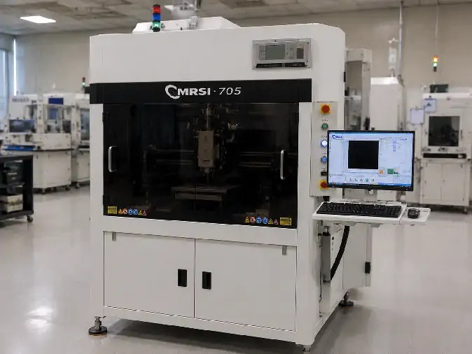
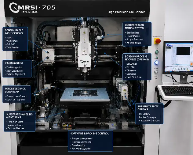
An effective MRSI-705 configuration begins with the assembly project, not with selecting the largest possible set of machine options. The same platform may be arranged around wafer input, waffle packs, Gel-Paks, tape-fed components, different bonding technologies and several production-flow strategies.
Official platform information identifies what may be configured, but it does not describe one standard machine. The appropriate arrangement follows the component, substrate, bonding material, alignment requirement, process sequence and production objective.
This guide explains how those project inputs translate into the material-handling, bonding, tooling, software and production areas that should be reviewed before an actual machine is selected.
Start With the Assembly Project
The first decision is not whether the machine needs a wafer feeder, dispensing system or optional tool turret. It is defining what the system must assemble, how the component is supplied and how the finished assembly should move through production.
| Project Input | Configuration Area Affected |
|---|---|
| Component dimensions, thickness and material | Pickup tool, ejector approach, handling path and permitted contact area |
| Input medium | Wafer handling, waffle-pack, Gel-Pak, tape or other presentation hardware |
| Substrate or package | Fixture, support, product flow and alignment method |
| Bonding material and joint method | Dispensing, stamping, heating, UV, force and tooling requirements |
| Accuracy and alignment requirement | Vision references, lighting, calibration and process control |
| Product mix and production volume | Tool strategy, material flow, recipes and integration mode |
These inputs should be considered together. A component may be easy to pick but difficult to align, while a technically suitable bonding method may become inefficient when the proposed substrate flow creates excessive handling or changeover work.
The purpose of the initial review is not to define every engineering parameter. It is to identify which parts of the platform need deeper investigation and which options would add little practical value.
Match Component Input, Wafer Handling and Substrate Flow
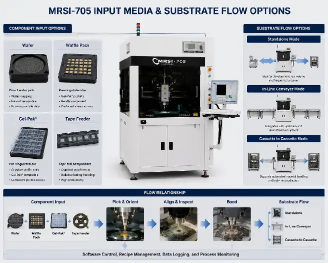
Component input and substrate transport are separate configuration decisions. The input source determines how the die or component is located, picked and oriented. Substrate flow determines how the assembly target is presented, supported and moved through production.
Pre-Singulated Component Input
Official MRSI-705 information includes input directions such as waffle packs, Gel-Paks and tape feeders. Each format creates a different relationship between component position, pickup access, orientation and changeover.
Waffle packs and Gel-Paks present individual parts in organized locations, but pocket geometry, surface condition and component orientation can affect tool access. Tape input introduces feeding, indexing and presentation hardware that must match the component and production sequence.
The choice should reflect more than loading convenience. It affects pickup-tool design, component identification, handling risk and the time required to move between products.
Direct Wafer Pickup and Die Selection
Direct wafer pickup becomes relevant when the project must select dies from a wafer rather than from an intermediate pack or tape. It can reduce additional handling and keep die-location information connected with the wafer process.
This route may require suitable wafer support, a feeder or loading method, an ejector system, pickup tooling and software that coordinates die-selection data with the physical wafer.
Depending on the process, die selection may use wafer mapping, ink-dot recognition or another approved method. A map can provide position and known-good-die information, while ink-dot recognition relies on visible marks produced during an upstream process.
The data and physical wafer must remain synchronized. Map orientation, die positions and selection logic must correspond to the wafer presented to the machine. Visible marks are useful only when the optics, lighting and recognition method can identify them reliably.
Thin dies, brittle materials and sensitive backside surfaces can also change the support, ejector and pickup requirements. Wafer dimensions, map formats and ejector arrangements should therefore be confirmed from the project rather than inferred from the model name.
Substrate and Package Flow
The substrate or package may be handled in standalone, in-line or cassette-to-cassette mode. These modes describe how the assembly target moves through production; they do not identify where the die comes from.
Standalone operation may suit development, frequent manual access or lower-volume work. In-line conveying can support coordination with surrounding equipment when controls and interfaces are compatible. Cassette handling may be appropriate when substrates are already organized around that production method.
No one flow is inherently superior. The choice follows the product format, handling risk, line architecture and expected changeover pattern.
Match the Bonding Process to the Required Modules
The bonding method affects material application, component handling, contact control, tooling and process sequence. Selecting the joint technology therefore defines several connected configuration decisions.
Eutectic Bonding
Eutectic bonding uses a controlled material and thermal process to form the joint. A suitable arrangement may involve heated tooling, a heated work area or another thermal method, together with process-specific tools and atmosphere control where the material system calls for it.
Temperature, force and timing belong to the qualified material process rather than to one universal MRSI-705 setting.
Epoxy Dispensing
Dispensing delivers bonding material through a pump, fluid path and needle or nozzle. The system should suit the material viscosity, required deposit geometry, cleaning method and production environment.
Material management and curing must also fit the intended sequence. A reference to epoxy die attach does not by itself confirm that the required dispensing equipment is installed.
Epoxy Stamping
Stamping transfers material through a dedicated tool rather than through a dispense nozzle. It may be useful when the process needs a defined transfer shape or controlled material pickup from a presentation surface.
Tool design, material presentation, transfer geometry and cleaning strategy determine whether stamping is practical. It serves a related purpose to dispensing, but the two methods are not interchangeable.
In-Situ UV Bonding
An in-situ UV process combines compatible bonding material with controlled placement and ultraviolet exposure. The machine arrangement must provide curing access while preserving component alignment through the exposure stage.
The material-application method, curing hardware and software sequence must work together around the selected adhesive process.
Flip-Chip Assembly
Flip-chip assembly places the active or interconnect side of the die toward the substrate. This can introduce die-orientation hardware, bottom-side vision, special pickup tools, substrate alignment and software that coordinates the complete handling sequence.
The exposed surface may also need protection during pickup and transfer, making tool contact and support part of the configuration decision.
Thermal-Compression Bonding
Thermal compression combines controlled heat and force with the required joint structure. The arrangement may involve heated tools, force feedback, height control and careful management of substrate support and coplanarity.
The exact hardware and process capability must be established from technical documentation and the machine being considered.
These process directions use different combinations of hardware, software, tooling and developed process conditions. They should not be treated as one standard package or assumed to operate together without engineering review.
Control Force, Height, Coplanarity and Alignment
Bonding quality depends on how the component approaches the target, how contact is detected and how the final placement condition is controlled. These factors connect the selected bonding technology with the machine’s motion, tooling and vision setup.
A place-to-force strategy uses a programmed force target to control contact. It can be useful where the component or joint needs a defined load, but the correct setting follows component strength, tool geometry and bonding method.
Place-to-height uses a positional or height-based endpoint. This may be suitable when the assembly geometry is stable, although substrate thickness, warpage and fixture variation can change the real contact condition.
Coplanarity must be considered at the same time. A tilted substrate, uneven support or poorly seated component can produce non-uniform contact even when the programmed height is reached correctly.
The alignment method should be designed around the features available on the component and target. Fiducial quality, surface contrast, lighting, bottom-side access, calibration and thermal movement can all influence the result. Vision is therefore part of the process-control strategy rather than an isolated camera option.
Select the Tooling and Tool-Change Strategy
A single assembly may require several tools. Pickup collets, placement tools, heated tools and stamping tools can serve different stages, while multichip products may introduce several component types within one recipe.
Modular tool banks may provide enough flexibility for R&D, NPI and lower-complexity production when the number of tools remains manageable and tool-change time is not a major cycle constraint.
Mycronic also describes an optional higher-volume turret that can hold up to 12 tools. It may be useful when several tools are used sequentially, product variety is high or repeated tool changes materially interrupt the process.
The turret is not standard, and additional tools do not automatically improve output. Bonding time, vision, curing, dispensing, material loading and substrate movement may remain the dominant cycle factors. For a stable product with limited tooling needs, a simpler arrangement may be easier to operate and maintain.
Configure the Production Environment
Software, Recipes and Traceability
Hardware modules become useful only when software can coordinate them as one repeatable process. Configuration review should cover the software version, licenses, process recipes, vision recipes, tool definitions and user-access structure.
Wafer processing may introduce map handling and die-selection logic. Product changeovers need controlled recipes and correct tool assignments. Material tracking or traceability may require product identification, production records and supported data exchange with other systems.
Backup and recovery also matter. A technically suitable machine can still create commissioning risk when recipes, calibration data or access credentials cannot be preserved and restored.
In-line production may add conveyor control and coordination with upstream or downstream equipment. An interface such as SMEMA should only be included in the project plan when documented for the relevant configuration. Host or factory-system communication likewise requires evidence from the actual software environment.
R&D, High-Mix and Volume Production
Research and process-development work usually benefits from flexible tooling, easy access and the ability to evaluate several material-input or bonding approaches. Frequent recipe changes are expected, and process evidence may matter more than maximum output.
High-mix or low- to medium-volume production places more emphasis on controlled changeover, multiple recipes, flexible input options and traceability. Several pickup tools may be useful without justifying the optional turret.
Higher-volume production can shift attention toward stable material flow, shorter tool-change delays, in-line or cassette handling and coordination with surrounding equipment. The optional turret may contribute where tool changes are a meaningful part of the cycle.
Volume alone does not determine the machine arrangement. Product mix, bonding duration, curing, inspection, component presentation and integration requirements can be equally influential, so throughput has little meaning without the complete process definition.
Verify the Proposed Configuration Before Selection
Before a machine is selected or quoted, compare the project with the installed input modules, wafer-processing hardware, tool banks or turret, pickup and bonding tools, vision environment and process modules.
The review should also cover heating, dispensing, stamping, UV equipment, flip-chip functions, software, licenses, recipes, substrate-handling mode, traceability and production integration. Platform support narrows the direction; the equipment record establishes what is present.
A representative sample or process evaluation may be useful when suitable tooling, materials, machine access and acceptance criteria are available. Such a trial can show whether the proposed arrangement deserves deeper engineering work, but its feasibility must first be established from the project and machine information.
To begin an MRSI-705 configuration review, contact the technical team by email or WhatsApp with the component dimensions, material, input format, substrate, bonding method, accuracy requirement, tooling needs, production volume and inspection or integration requirements.
Wafer information, drawings, component photographs, substrate files, tooling images and process documents can be attached after the conversation is opened. Compatibility, conversion feasibility, testing scope, throughput, price and delivery should follow the technical review.
Frequently Asked Questions About MRSI-705 Configuration
What information is needed to configure an MRSI-705?
Start with the component dimensions, thickness and material, input format, substrate, bonding material, bonding method, accuracy requirement, tooling, inspection needs, product mix and expected production volume.
What material-input formats can the MRSI-705 use?
Official platform information includes wafer, waffle-pack, Gel-Pak and tape-input directions. The feeder, support, indexing and pickup hardware needed for the project must be checked against the proposed configuration.
Can the MRSI-705 pick die directly from a wafer?
Direct wafer pickup may be configured when suitable wafer support, ejector hardware, pickup tooling and compatible mapping or ink-dot selection functions are available.
What is the difference between epoxy dispensing and epoxy stamping?
Dispensing delivers material through a pump and nozzle, while stamping transfers it with a dedicated tool. The appropriate method follows the material, deposit geometry, process control and production requirements.
What is required for flip-chip assembly?
A flip-chip configuration may involve die-orientation hardware, bottom-side vision, suitable tooling, substrate alignment, software recipes and protection of the active die surface.
Is the 12-tool turret standard on the MRSI-705?
No. It is an optional higher-volume configuration. Its value depends on the number of tools, process sequence, changeover pattern and other cycle constraints.
Conclusion: MRSI-705 configuration begins with the product and process rather than the number of available options. Component input, wafer handling and substrate flow must be planned separately, while each bonding method introduces its own material, tooling and control requirements. Force, height, coplanarity and alignment should be treated as one process-control problem, and tooling, software and production mode should follow the real product mix. The most highly optioned machine is not automatically the best fit; final suitability depends on comparing the actual assembly project with the proposed machine configuration.