Selecting a die bonding machine begins with the attachment process required by the product. Epoxy, eutectic solder, soft solder and silver sintering can all be described as die bonding, but they do not require the same material-delivery system, bond head, heating method, atmosphere, force control or downstream equipment.
A machine that can pick and accurately place a die is therefore not automatically capable of completing the required die attach process. The die backside, substrate finish, thermal path, electrical connection, bond-line requirement and production volume must be considered before individual machine models are compared.
The practical selection task is to connect the product requirement with the bonding material, process sequence and installed machine configuration.
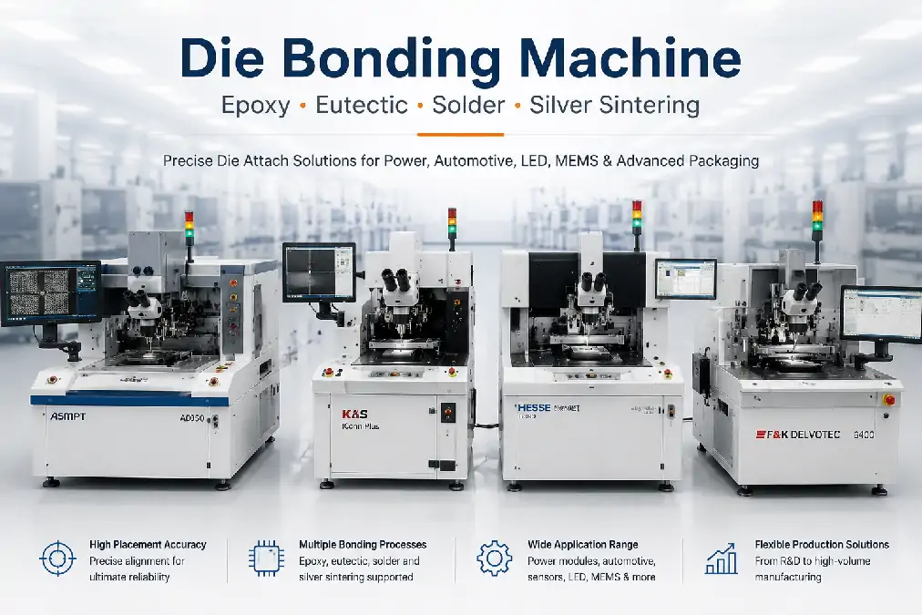
Start with the Required Die Attach Result
The bonding method should follow the function of the final assembly. A low-cost sensor package, a high-power SiC module and a precision laser assembly may all require die placement, but their thermal, electrical and mechanical requirements can lead to very different equipment directions.
| Product Requirement | Questions to Define | Why It Changes Machine Selection |
|---|---|---|
| Thermal path | How much heat must move from the die into the substrate or heat spreader? | The required thermal performance influences whether epoxy, solder, eutectic or sintered material is suitable. |
| Electrical connection | Must the bond layer conduct current, remain electrically isolated or provide only mechanical support? | Conductive and non-conductive materials require different dispensing, curing and qualification plans. |
| Die and substrate materials | What are the die backside metallization, substrate finish and surface conditions? | The material interface affects wetting, adhesion, diffusion, oxidation control and process temperature. |
| Bond-line control | What thickness, uniformity and die tilt are acceptable? | Dispensing, stamping, preforms, force control and tooling must produce the required bond layer. |
| Void requirement | How much voiding can the thermal and reliability design tolerate? | Material preparation, scrub, atmosphere, reflow and downstream vacuum processing may become important. |
| Package sensitivity | How much force, heat and mechanical movement can the die and substrate withstand? | Thin dies, brittle materials and delicate structures may require specialized pickup, support and force control. |
| Production model | Is the project R&D, high-mix production or high-volume manufacturing? | The required automation, tool changing, material handling and output may be as important as the bonding process. |
These requirements should be defined before a buyer asks whether a particular die bonder is “epoxy capable” or “sintering capable.” The same process name can still require different machine modules for different packages.
How the Main Die Bonding Processes Differ
| Bonding Process | How the Bond Is Formed | Typical Machine Requirements | Main Selection Concern |
|---|---|---|---|
| Epoxy die bonding | A conductive or non-conductive adhesive is deposited, the die is placed and the material is cured. | Dispensing, jetting, stamping or dipping; placement-force control; bond-line control; curing plan | Material volume, bleed, die tilt, cure condition and bond-line consistency |
| Eutectic die bonding | A defined alloy or preform is heated through its bonding range to create a metallic joint. | Controlled heating and cooling, atmosphere control, preform handling and optional scrub | Temperature profile, oxidation, wetting, voiding and die movement during bonding |
| Soft solder die bonding | Solder is applied and reflowed to create a conductive thermal and electrical connection. | Solder preparation or dispensing, heated process zones, atmosphere control and high-volume leadframe handling | Solder thickness, wetting, voiding, oxidation and production repeatability |
| Silver sintering | Silver particles form a dense connection through a diffusion-based sintering process rather than conventional curing or solder reflow. | Paste or film handling, precise bond-line control, heated stage, controlled force where applicable and downstream sintering | Material preparation, bond-line thickness, tacking stability, pressure route and final sintering conditions |
The table identifies the main equipment direction. It does not define a universal process recipe. The exact configuration depends on the selected material, die, substrate, production route and qualification requirement.
Epoxy Die Bonding Prioritizes Material Control and Curing
Epoxy is widely used because it can support many package formats and can be deposited through several methods. Conductive epoxy may provide electrical and thermal connection, while non-conductive material may provide mechanical attachment or electrical isolation.
The die bonder may apply epoxy through:
Time-pressure dispensing
Auger dispensing
Jet dispensing
Pin transfer or stamping
Die dipping
Pre-applied adhesive material
The correct method depends on material viscosity, filler content, deposit size, pattern, package geometry and production speed. A dispenser that works with one epoxy should not be assumed to handle every filled or unfilled formulation.
Important Epoxy Machine Functions
Stable dispensing or stamping volume
Material-temperature and pot-life control where required
Accurate die placement before the material moves or cures
Programmable placement force and bond height
Bond-line thickness and die-tilt control
Pre-bond and post-bond vision inspection
Reliable transfer to the required cure process
Epoxy placement often uses lower process temperatures than metallic soldering routes, but the complete assembly still depends on the specified cure profile. A successful placement does not prove that the final cured joint will meet thermal, electrical or reliability requirements.
For a current example of a high-speed epoxy platform, the BESI ESEC 2100 hS die bonder can be reviewed as one equipment direction. Its actual suitability still depends on the offered machine configuration and target package.
Eutectic Die Bonding Requires Controlled Heat and Surface Conditions
Eutectic die bonding creates a metallic attachment by heating an alloy or preform through a defined bonding condition. The process is often considered where the product needs strong thermal transfer, electrical conduction, high placement accuracy or a controlled metallic joint.
The machine and tooling may need to support:
Predeposited solder or separate preform handling
Rapid and repeatable heating and cooling
Controlled inert or reducing atmosphere where required
Programmable scrub or die movement
Accurate bond force and bond height
Tooling that remains stable at process temperature
Vision alignment before the surfaces become obscured
Scrub can help disturb surface films, improve wetting and reduce trapped gas in applicable processes. It should not be treated as a universal requirement or a substitute for correct surface preparation and temperature control.
The eutectic process must also consider how the die behaves while the alloy is molten. Poor support, excessive movement or an unsuitable thermal profile can affect alignment, bond-line thickness and void formation.
Soft Solder Die Bonding Is Closely Connected to Power Production
Soft solder die bonding is commonly evaluated for power semiconductor and high-volume leadframe applications that require a conductive thermal path between the die and its carrier.
Although both eutectic and soft solder processes use metallic materials and heat, they should not be treated as identical. The solder form, melting behavior, dispensing route, atmosphere, leadframe transport and production sequence may differ substantially.
Soft Solder Equipment Areas to Confirm
Solder-wire, paste, preform or other material-delivery method
Dispensing or solder preparation consistency
Heated bond head, stage or process zone
Gas and oxidation-control arrangement
Die pickup and placement while the solder is in process
Leadframe, strip or power-module handling
Process visualization and defect monitoring
Cooling and transfer after bonding
High-volume soft solder equipment is often more application-specific than a flexible R&D die bonder. A buyer replacing an existing production machine should compare the complete material and leadframe route, not only placement accuracy and maximum output.
Silver Sintering Requires a Complete Tacking and Sintering Route
Silver sintering is increasingly used where power devices require high thermal performance and long-term operation under demanding temperature conditions. The material does not form its final joint through conventional epoxy curing or solder melting.
Depending on the selected material and production process, the route may include:
Applying silver paste, film or another sintering material to the substrate or die
Picking and accurately placing the die
Controlling the initial bond-line thickness
Tacking the die so it remains stable during transport
Transferring the assembly to a pressure or pressureless sintering process
Applying the required combination of heat, force, atmosphere and time
Some processes use high-force tacking or pressure-assisted sintering, while others use pressureless materials. The selected die bonder must therefore be matched to the actual material route rather than to the general term “silver sintering.”
Important equipment considerations include:
Paste dispensing, film stamping or transfer-film handling
Thin-die pickup and support
Heated bond head and stage capability
Programmable bond force
Bond-line thickness and die-tilt control
Automatic tool changing for different dies and products
Stable handoff to the final sintering press or furnace
A die bonder may perform the placement and tacking stages without completing the final sintered joint. The full production line must therefore be reviewed, not only the pick-and-place machine.
Material Flow Can Be as Important as the Bonding Method
After the process direction is defined, confirm how the die, bonding material and substrate enter the machine.
| Material Area | Possible Input Formats | Machine Consequence |
|---|---|---|
| Die input | Wafer frame, waffle pack, Gel-Pak, tray, tape-and-reel or loose die | Changes ejector, pickup tool, vision, feeder and automatic changeover requirements. |
| Bonding material | Epoxy, solder paste, wire, preform, silver paste, film or pre-applied layer | Changes dispenser, stamping tool, dipping unit, heater and material-control system. |
| Substrate | Leadframe, DBC, AMB, ceramic, PCB, carrier, package or individual submount | Changes workholder, indexing, clamping, heating and production automation. |
| Product changeover | Single product, high mix, multiple dies or multiple process materials | May require automatic tool, ejector, wafer and recipe changing. |
A multi-process platform may support several bonding methods, but only when the required dispensers, heaters, heads, tools, atmosphere controls and software options are actually installed.
The BESI Datacon 2200 EVO die bonding machine illustrates how wafer handling, tool changing, dispensing and hot or cold processes can be combined within a flexible platform. The configuration of an offered machine still needs to be verified individually.
A Practical Die Bonding Machine Selection Sequence
Define the final joint. Establish the thermal, electrical, mechanical and reliability requirements.
Confirm the material interfaces. Identify die backside metallization, substrate finish and surface condition.
Select the bonding process. Compare epoxy, eutectic, soft solder and sintering against the required joint.
Define material presentation. Record how the die, bonding material and substrate enter the machine.
Identify process modules. Confirm dispensing, stamping, preform handling, heating, atmosphere, scrub, force and cooling requirements.
Set the placement requirement. Define accuracy, theta, bond height, die tilt and post-bond inspection.
Review production automation. Establish output, changeover, traceability and handler requirements.
Check the exact machine. Compare the installed configuration, software, tools and accessories with the process plan.
Run representative material. Verify the complete material and bonding sequence under agreed test conditions.
Qualify the final joint. Confirm thermal, electrical, mechanical and reliability results through the applicable product process.
This sequence is the core machine-selection decision. The bonding method determines which equipment functions are necessary, while the exact product determines whether those functions are sufficient.
When a Multi-Process Die Bonder Makes Sense
A flexible die bonding machine may be valuable when the factory runs high-mix products, performs process development or needs several bonding routes within one platform.
Multi-process capability is most useful when:
The installed heads and tools cover the required die range.
The machine can change among the required material-input formats.
Dispensing, stamping, heating and atmosphere modules are available.
Software and recipes support controlled process changeover.
The expected output remains practical after changeovers.
Calibration and maintenance can be managed across the different processes.
A dedicated high-volume machine may be more suitable when one product family dominates production and requires specialized leadframe handling, soft solder control or high-force sintering preparation.
Die Bonding Machine Selection FAQ
Can one die bonding machine run epoxy and eutectic processes?
Some flexible platforms can support both, but only when the required dispenser, heating system, atmosphere control, tooling and software are installed. The model name alone does not confirm multi-process capability.
Is silver sintering completed entirely inside a die bonder?
Not always. The die bonder may apply material, place the die and perform tacking, while final sintering occurs in a separate pressure or pressureless process. The complete line should be reviewed.
Is eutectic bonding the same as soft solder die attach?
No. Both use metallic bonding materials and heat, but alloy behavior, material presentation, atmosphere, tooling and production equipment can differ. The required process should be defined by the package and material system.
Does higher placement accuracy mean a better die bonding machine?
Not by itself. Accuracy must be considered together with die handling, bond-line control, material application, force, heating, automation and the actual measurement conditions.
What information should be prepared before requesting a die
Selecting a die bonding machine begins with the attachment process required by the product. Epoxy, eutectic solder, soft solder and silver sintering can all be described as die bonding, but they do not require the same material-delivery system, bond head, heating method, atmosphere, force control or downstream equipment.
A machine that can pick and accurately place a die is therefore not automatically capable of completing the required die attach process. The die backside, substrate finish, thermal path, electrical connection, bond-line requirement and production volume must be considered before individual machine models are compared.
The practical selection task is to connect the product requirement with the bonding material, process sequence and installed machine configuration.
Start with the Required Die Attach Result
The bonding method should follow the function of the final assembly. A low-cost sensor package, a high-power SiC module and a precision laser assembly may all require die placement, but their thermal, electrical and mechanical requirements can lead to very different equipment directions.
| Product Requirement | Questions to Define | Why It Changes Machine Selection |
|---|---|---|
| Thermal path | How much heat must move from the die into the substrate or heat spreader? | The required thermal performance influences whether epoxy, solder, eutectic or sintered material is suitable. |
| Electrical connection | Must the bond layer conduct current, remain electrically isolated or provide only mechanical support? | Conductive and non-conductive materials require different dispensing, curing and qualification plans. |
| Die and substrate materials | What are the die backside metallization, substrate finish and surface conditions? | The material interface affects wetting, adhesion, diffusion, oxidation control and process temperature. |
| Bond-line control | What thickness, uniformity and die tilt are acceptable? | Dispensing, stamping, preforms, force control and tooling must produce the required bond layer. |
| Void requirement | How much voiding can the thermal and reliability design tolerate? | Material preparation, scrub, atmosphere, reflow and downstream vacuum processing may become important. |
| Package sensitivity | How much force, heat and mechanical movement can the die and substrate withstand? | Thin dies, brittle materials and delicate structures may require specialized pickup, support and force control. |
| Production model | Is the project R&D, high-mix production or high-volume manufacturing? | The required automation, tool changing, material handling and output may be as important as the bonding process. |
These requirements should be defined before a buyer asks whether a particular die bonder is “epoxy capable” or “sintering capable.” The same process name can still require different machine modules for different packages.
How the Main Die Bonding Processes Differ
| Bonding Process | How the Bond Is Formed | Typical Machine Requirements | Main Selection Concern |
|---|---|---|---|
| Epoxy die bonding | A conductive or non-conductive adhesive is deposited, the die is placed and the material is cured. | Dispensing, jetting, stamping or dipping; placement-force control; bond-line control; curing plan | Material volume, bleed, die tilt, cure condition and bond-line consistency |
| Eutectic die bonding | A defined alloy or preform is heated through its bonding range to create a metallic joint. | Controlled heating and cooling, atmosphere control, preform handling and optional scrub | Temperature profile, oxidation, wetting, voiding and die movement during bonding |
| Soft solder die bonding | Solder is applied and reflowed to create a conductive thermal and electrical connection. | Solder preparation or dispensing, heated process zones, atmosphere control and high-volume leadframe handling | Solder thickness, wetting, voiding, oxidation and production repeatability |
| Silver sintering | Silver particles form a dense connection through a diffusion-based sintering process rather than conventional curing or solder reflow. | Paste or film handling, precise bond-line control, heated stage, controlled force where applicable and downstream sintering | Material preparation, bond-line thickness, tacking stability, pressure route and final sintering conditions |
The table identifies the main equipment direction. It does not define a universal process recipe. The exact configuration depends on the selected material, die, substrate, production route and qualification requirement.
Epoxy Die Bonding Prioritizes Material Control and Curing
Epoxy is widely used because it can support many package formats and can be deposited through several methods. Conductive epoxy may provide electrical and thermal connection, while non-conductive material may provide mechanical attachment or electrical isolation.
The die bonder may apply epoxy through:
Time-pressure dispensing
Auger dispensing
Jet dispensing
Pin transfer or stamping
Die dipping
Pre-applied adhesive material
The correct method depends on material viscosity, filler content, deposit size, pattern, package geometry and production speed. A dispenser that works with one epoxy should not be assumed to handle every filled or unfilled formulation.
Important Epoxy Machine Functions
Stable dispensing or stamping volume
Material-temperature and pot-life control where required
Accurate die placement before the material moves or cures
Programmable placement force and bond height
Bond-line thickness and die-tilt control
Pre-bond and post-bond vision inspection
Reliable transfer to the required cure process
Epoxy placement often uses lower process temperatures than metallic soldering routes, but the complete assembly still depends on the specified cure profile. A successful placement does not prove that the final cured joint will meet thermal, electrical or reliability requirements.
For a current example of a high-speed epoxy platform, the BESI ESEC 2100 hS die bonder can be reviewed as one equipment direction. Its actual suitability still depends on the offered machine configuration and target package.
Eutectic Die Bonding Requires Controlled Heat and Surface Conditions
Eutectic die bonding creates a metallic attachment by heating an alloy or preform through a defined bonding condition. The process is often considered where the product needs strong thermal transfer, electrical conduction, high placement accuracy or a controlled metallic joint.
The machine and tooling may need to support:
Predeposited solder or separate preform handling
Rapid and repeatable heating and cooling
Controlled inert or reducing atmosphere where required
Programmable scrub or die movement
Accurate bond force and bond height
Tooling that remains stable at process temperature
Vision alignment before the surfaces become obscured
Scrub can help disturb surface films, improve wetting and reduce trapped gas in applicable processes. It should not be treated as a universal requirement or a substitute for correct surface preparation and temperature control.
The eutectic process must also consider how the die behaves while the alloy is molten. Poor support, excessive movement or an unsuitable thermal profile can affect alignment, bond-line thickness and void formation.
Soft Solder Die Bonding Is Closely Connected to Power Production
Soft solder die bonding is commonly evaluated for power semiconductor and high-volume leadframe applications that require a conductive thermal path between the die and its carrier.
Although both eutectic and soft solder processes use metallic materials and heat, they should not be treated as identical. The solder form, melting behavior, dispensing route, atmosphere, leadframe transport and production sequence may differ substantially.
Soft Solder Equipment Areas to Confirm
Solder-wire, paste, preform or other material-delivery method
Dispensing or solder preparation consistency
Heated bond head, stage or process zone
Gas and oxidation-control arrangement
Die pickup and placement while the solder is in process
Leadframe, strip or power-module handling
Process visualization and defect monitoring
Cooling and transfer after bonding
High-volume soft solder equipment is often more application-specific than a flexible R&D die bonder. A buyer replacing an existing production machine should compare the complete material and leadframe route, not only placement accuracy and maximum output.
Silver Sintering Requires a Complete Tacking and Sintering Route
Silver sintering is increasingly used where power devices require high thermal performance and long-term operation under demanding temperature conditions. The material does not form its final joint through conventional epoxy curing or solder melting.
Depending on the selected material and production process, the route may include:
Applying silver paste, film or another sintering material to the substrate or die
Picking and accurately placing the die
Controlling the initial bond-line thickness
Tacking the die so it remains stable during transport
Transferring the assembly to a pressure or pressureless sintering process
Applying the required combination of heat, force, atmosphere and time
Some processes use high-force tacking or pressure-assisted sintering, while others use pressureless materials. The selected die bonder must therefore be matched to the actual material route rather than to the general term “silver sintering.”
Important equipment considerations include:
Paste dispensing, film stamping or transfer-film handling
Thin-die pickup and support
Heated bond head and stage capability
Programmable bond force
Bond-line thickness and die-tilt control
Automatic tool changing for different dies and products
Stable handoff to the final sintering press or furnace
A die bonder may perform the placement and tacking stages without completing the final sintered joint. The full production line must therefore be reviewed, not only the pick-and-place machine.
Material Flow Can Be as Important as the Bonding Method
After the process direction is defined, confirm how the die, bonding material and substrate enter the machine.
| Material Area | Possible Input Formats | Machine Consequence |
|---|---|---|
| Die input | Wafer frame, waffle pack, Gel-Pak, tray, tape-and-reel or loose die | Changes ejector, pickup tool, vision, feeder and automatic changeover requirements. |
| Bonding material | Epoxy, solder paste, wire, preform, silver paste, film or pre-applied layer | Changes dispenser, stamping tool, dipping unit, heater and material-control system. |
| Substrate | Leadframe, DBC, AMB, ceramic, PCB, carrier, package or individual submount | Changes workholder, indexing, clamping, heating and production automation. |
| Product changeover | Single product, high mix, multiple dies or multiple process materials | May require automatic tool, ejector, wafer and recipe changing. |
A multi-process platform may support several bonding methods, but only when the required dispensers, heaters, heads, tools, atmosphere controls and software options are actually installed.
The BESI Datacon 2200 EVO die bonding machine illustrates how wafer handling, tool changing, dispensing and hot or cold processes can be combined within a flexible platform. The configuration of an offered machine still needs to be verified individually.
A Practical Die Bonding Machine Selection Sequence
Define the final joint. Establish the thermal, electrical, mechanical and reliability requirements.
Confirm the material interfaces. Identify die backside metallization, substrate finish and surface condition.
Select the bonding process. Compare epoxy, eutectic, soft solder and sintering against the required joint.
Define material presentation. Record how the die, bonding material and substrate enter the machine.
Identify process modules. Confirm dispensing, stamping, preform handling, heating, atmosphere, scrub, force and cooling requirements.
Set the placement requirement. Define accuracy, theta, bond height, die tilt and post-bond inspection.
Review production automation. Establish output, changeover, traceability and handler requirements.
Check the exact machine. Compare the installed configuration, software, tools and accessories with the process plan.
Run representative material. Verify the complete material and bonding sequence under agreed test conditions.
Qualify the final joint. Confirm thermal, electrical, mechanical and reliability results through the applicable product process.
This sequence is the core machine-selection decision. The bonding method determines which equipment functions are necessary, while the exact product determines whether those functions are sufficient.
When a Multi-Process Die Bonder Makes Sense
A flexible die bonding machine may be valuable when the factory runs high-mix products, performs process development or needs several bonding routes within one platform.
Multi-process capability is most useful when:
The installed heads and tools cover the required die range.
The machine can change among the required material-input formats.
Dispensing, stamping, heating and atmosphere modules are available.
Software and recipes support controlled process changeover.
The expected output remains practical after changeovers.
Calibration and maintenance can be managed across the different processes.
A dedicated high-volume machine may be more suitable when one product family dominates production and requires specialized leadframe handling, soft solder control or high-force sintering preparation.
Die Bonding Machine Selection FAQ
Can one die bonding machine run epoxy and eutectic processes?
Some flexible platforms can support both, but only when the required dispenser, heating system, atmosphere control, tooling and software are installed. The model name alone does not confirm multi-process capability.
Is silver sintering completed entirely inside a die bonder?
Not always. The die bonder may apply material, place the die and perform tacking, while final sintering occurs in a separate pressure or pressureless process. The complete line should be reviewed.
Is eutectic bonding the same as soft solder die attach?
No. Both use metallic bonding materials and heat, but alloy behavior, material presentation, atmosphere, tooling and production equipment can differ. The required process should be defined by the package and material system.
Does higher placement accuracy mean a better die bonding machine?
Not by itself. Accuracy must be considered together with die handling, bond-line control, material application, force, heating, automation and the actual measurement conditions.
What information should be prepared before requesting a die bonder recommendation?
Prepare the die dimensions and thickness, input format, substrate, bonding material, placement requirement, bond force, temperature, atmosphere, production target and required inspection or traceability functions.
Final Recommendation
A die bonding machine should be selected by the joint it must create, not only by its speed, accuracy or model name. Epoxy processes depend heavily on material deposition and curing. Eutectic and soft solder processes require controlled metallic bonding conditions. Silver sintering requires precise material preparation, tacking and a complete sintering route.
Review available die bonding machines only after the process, material flow and required modules are defined. To discuss a project, send the die, substrate, bonding material, production target and intended process through the All-SMT equipment inquiry page.
bonder recommendation?
Prepare the die dimensions and thickness, input format, substrate, bonding material, placement requirement, bond force, temperature, atmosphere, production target and required inspection or traceability functions.
Final Recommendation
A die bonding machine should be selected by the joint it must create, not only by its speed, accuracy or model name. Epoxy processes depend heavily on material deposition and curing. Eutectic and soft solder processes require controlled metallic bonding conditions. Silver sintering requires precise material preparation, tacking and a complete sintering route.
Review available die bonding machines only after the process, material flow and required modules are defined. To discuss a project, send the die, substrate, bonding material, production target and intended process through the All-SMT equipment inquiry page.