1. Product Overview and Core Advantages
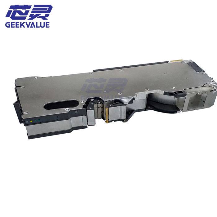
1.1 Product Positioning
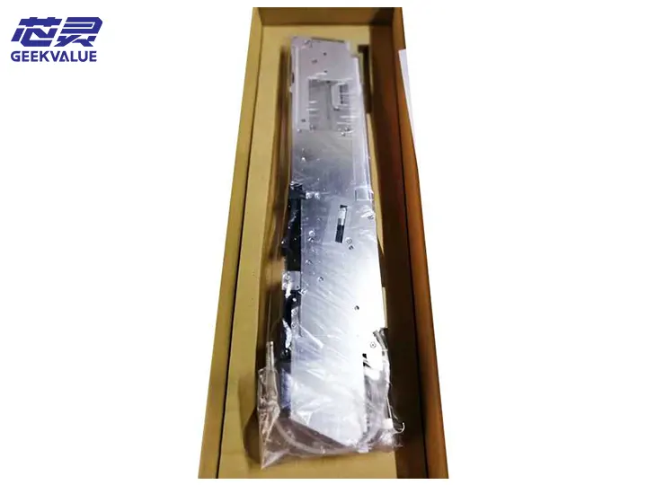
Siemens 3×8 SL Feeder (Model: 00141088) is a three-channel synchronous feeding device designed for efficient processing of 8mm tapes. It can simultaneously feed three different components, significantly improving the placement efficiency and flexibility of SMT production lines.
1.2 Core advantages
Three-in-one efficient design: single feeder realizes synchronous supply of three components, saving station space
Intelligent channel management: independent control of feeding action of each channel
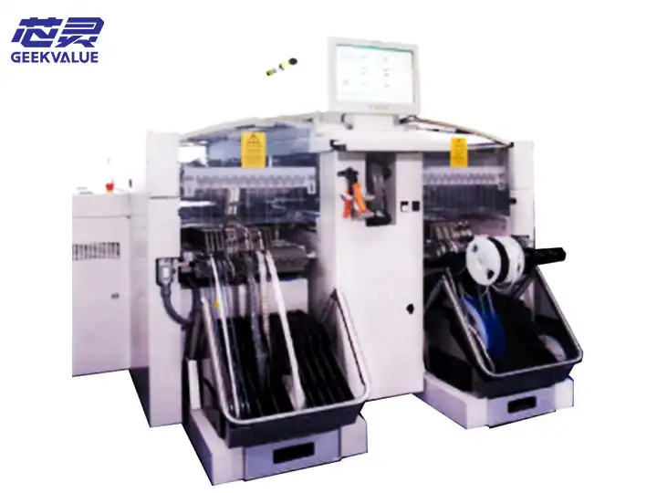
Ultra-high compatibility: compatible with SIPLACE full range of placement machines
Precise feeding: step accuracy ±0.04mm (@23±1℃)
Quick material change: patent unlocking design, material change time <8 seconds
Long life structure: key component life ≥10 million times
II. Technical specifications and structural features
2.1 Basic parameters
Item Parameter value
Tape width 3×8mm (independent per channel)
Feeding step 2/4/8mm (programmable)
Maximum component height 3mm (per channel)
Tape thickness range 0.1-0.5mm
Feeding speed 45 times/minute (maximum)
Power supply voltage 24VDC±5%
Communication interface RS-485
Protection level IP54
Weight 1.2kg
2.2 Mechanical structure features
Three-channel independent system:
Independent stepper motor drive (0.9° step angle per channel)
Modular feeding mechanism (can be replaced separately)
Guide mechanism:
Precision ceramic guide rail (hardness HV1500)
Segmented pressing device (3 pressure points per channel)
Sensor system:
Hall sensor detects feeding position
Optical sensor monitors material belt status (optional)
Quick changeover design:
Single-hand operation of material belt release mechanism
Color-coded channel (red/blue/green)
III. Core functions and production line value
3.1 Intelligent functions
Independent channel control:
Programmable setting of feeding step distance for each channel
Support mixed feeding of different components
Status monitoring:
Material belt remaining amount detection
Feeding abnormal warning
Channel usage statistics
Data management:
Store feeding counts for each channel
Record the latest 50 alarm information
3.2 Production line value
Space saving: Reduce the need for 2 feeder stations
Efficiency improvement: Reduce material change frequency by 67%
Cost optimization: Reduce equipment investment by 40%
Flexible production: Quick response to product changeover
IV. Application scenarios
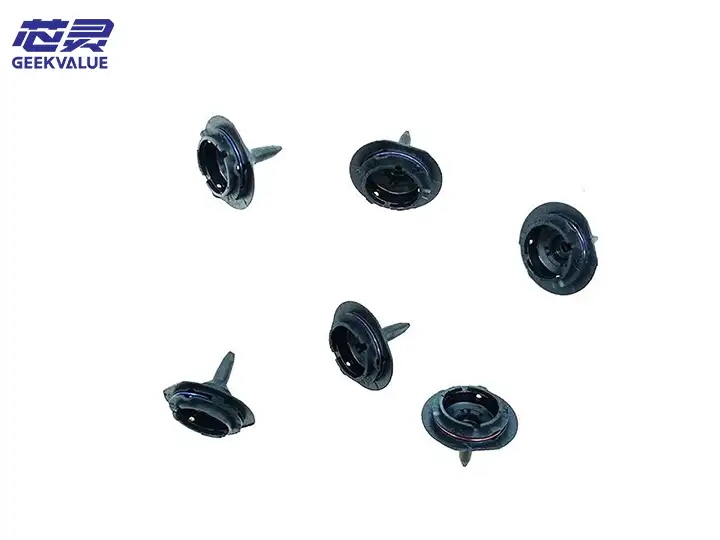
4.1 Typical application components
Resistor/capacitor array
Transistor combination
LED RGB component
Small connector group
Sensor module
4.2 Applicable industries
Consumer electronics
Automotive electronic control unit
Internet of Things equipment
Medical electronic
Industrial control module
V. Common errors and solutions
5.1 Fault code quick reference table
Code Fault description Possible cause Professional solution
E301 Channel 1 feeding failure 1. Material tape stuck
2. Motor failure 1. Check material tape path
2. Test motor winding (should be 8±0.5Ω)
E302 Channel 2 sensor abnormality 1. Contamination
2. Poor connection 1. Clean sensor window
2. Check FPC connector
E303 Communication interruption 1. Cable damage
2. Terminal resistance 1. Check RS-485 line
2. Confirm 120Ω terminal resistance
E304 Channel 3 position deviation 1. Parameter error
2. Gear wear 1. Recalibrate
2. Check gear meshing clearance
E305 Multi-channel conflict 1. Program error
2. Signal interference 1. Check feeding timing
2. Add shielding measures
5.2 Channel-specific diagnostics
Channel isolation test:
Activate each channel individually through HMI
Observe whether the feeding action is smooth
Current waveform analysis:
Normal current range: 0.6-1.2A
Abnormal waveform indicates mechanical resistance
Optical inspection:
Use a magnifying glass to observe rail wear
Check the damage of the belt tooth holes
VI. Maintenance Specifications
6.1 Daily Maintenance
Cleaning:
Wipe the surface of the feeder with a dust-free cloth every day
Clean the guide rail debris with an air gun every week (pressure ≤ 0.15MPa)
Lubrication Management:
Monthly Lubrication:
Guide Rail: Kluber ISOFLEX NBU15 (0.1g/channel)
Gear: Molykote EM-30L (brush coating method)
Inspection Points:
Confirm the pressure force of each channel every day
Check the connector status every week
6.2 Regular Deep Maintenance
Perform Quarterly:
Disassemble and clean the feeding mechanism of each channel
Calibrate the parallelism of the channel (special fixture required)
Test the sensor response time (should be <5ms)
Replace the worn bushing (maximum allowable clearance 0.02mm)
Annual Maintenance:
Fully replace the worn parts:
Feeding gear set
Pressure spring
Electrical system insulation detection
Firmware upgrade and parameter optimization
VII. Common faults and maintenance ideas
7.1 Typical fault analysis
Multi-channel asynchrony:
Check the main control board clock signal
Verify the motor drive current of each channel
Single channel failure:
Measure the channel power supply voltage (should be 24±0.5V)
Check the photocoupler status
Inaccurate tape positioning:
Adjust the parallelism of the guide rail
Replace the worn ratchet
7.2 Maintenance flow chart
text
Start → Phenomenon confirmation → Channel isolation test → Electrical detection → Mechanical inspection
↓ ↓ ↓ ↓
HMI diagnosis → Replace the control board → Repair the drive circuit → Replace the mechanical parts
↓
Parameter calibration → Functional test → End
VIII. Technology evolution and upgrade suggestions
8.1 Version iteration
2015 first generation: basic three-channel feeder
2017 second generation: Improve the guide rail system
2019 third generation: current intelligent version
2022 fourth generation (planned): integrated visual inspection
8.2 Upgrade path
Hardware upgrade:
Optional high-precision encoder
Upgrade to CAN bus communication
Software upgrade:
Install Advanced Channel Management Suite
Enable predictive maintenance function
System integration:
Interconnect MES system
Remote monitoring
IX. Comparison analysis with competitors
Comparison items 3×8 SL Feeder Competitor A Competitor B
Channel independence Fully independent Semi-independent Linkage
Feeding accuracy ±0.04mm ±0.06mm ±0.1mm
Replacement time <8 seconds 12 seconds 15 seconds
Communication interface RS-485 CAN RS-232
Life cycle cost $0.002/time $0.003/time $0.005/time
X. Usage suggestions and summary
10.1 Best practices
Parameter optimization:
Establish channel parameter templates for different components
Enable "Soft Feed" function protects precision components
Environmental control:
Maintain temperature at 20-26℃
Control humidity at 30-70%RH
Spare parts strategy:
Standby key components:
Channel gear set (P/N: 00141089)
Sensor module (P/N: 00141090)
10.2 Summary
Siemens 3×8 SL Feeder 00141088 has become an ideal choice for high-density SMT production with its innovative three-channel design, excellent space utilization and precise feeding performance. Its outstanding features include:
Efficiency revolution: single feeder achieves three times feeding capacity
Intelligent control: manage each channel independently
Reliable and durable: military-grade mechanical structure
Future development direction:
Integrated AI channel optimization algorithm
Use self-lubricating composite materials
Achieve wireless parameter configuration
Recommend users:
Establish a channel use rotation system
Perform mechanical precision verification regularly
Train professional maintenance team
The equipment is particularly suitable for:
Smartphone motherboard production
Automotive electronic control module
High-density electronic assembly
Multi-variety small batch production
Through scientific use and professional maintenance, the 3×8 SL feeder can ensure long-term stable operation and provide a reliable multi-component feeding solution for efficient SMT production.