EN
EN id
id sk
sk sr
sr sv
sv it
it pt
pt bn
bn ms
ms be
be nl
nl fr
fr th
th vi
vi ru
ru ja
ja ko
ko de
de hy
hy az
az bs
bs bg
bg my
my cs
cs da
da dv
dv el
el et
et fil
fil fi
fi ga
ga gl
gl gn
gn he
he hi
hi km
km hr
hr hu
hu is
is kn
kn rw
rw lo
lo lv
lv lt
lt lb
lb lg
lg mi
mi mt
mt ne
ne no
no ny
ny or
or om
om per
per pl
pl ro
ro sa
sa so
so es
es sw
sw ta
ta tr
tr uk
uk ur
ur cy
cy xh
xh
An ASM 8mm feeder should be checked before a reel changeover, not only after a placement fault occurs. Whether the feeder is a standard configuration or supplied with a sensor or splice-related function, stable production depends on correct tape loading, reel seating, tape routing, cover tape handling, feeder recognition, component orientation and a controlled first-article verification.
Buyers and SMT engineers searching for an ASM 8mm feeder sensor, SIPLACE 8mm feeder splice sensor, 00141290 feeder, 00141390 feeder, 00141490 feeder or an ASM feeder changeover guide often focus only on whether the feeder has a sensor feature.
The more important question is whether the full feeder, reel and tape setup is ready to run reliably on the actual production line.
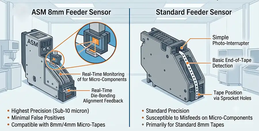
In Brief: What Is the Difference Between a Standard and Sensor-Related 8mm Feeder Setup?
A standard feeder setup is primarily evaluated by its mechanical tape-feed path, sprocket movement, cover tape route, interface, latch condition and placement-machine recognition. A sensor or splice-related feeder setup adds another configuration area that must also be verified: the actual sensor module, signal behavior, feeder identification and relevant machine-side recognition.
Sensor-related configuration does not remove the need for normal tape-path checks.
Correct reel loading remains critical even when a feeder includes additional sensing capability.
Splice-related production changes should be verified before full placement output is released.
First-article confirmation is still required after feeder setup or reel changeover.
Why 8mm Width Does Not Define Feeder Function
Two feeders can both be described as 8mm while serving different equipment families, revision levels or sensor-related configurations. Tape width confirms only one part of the component delivery route. It does not confirm sensor condition, splice-related setup, feeder recognition, tape pitch handling, cover tape path or machine compatibility.
Production rule: Verify the feeder, tape and machine relationship as one setup before production release.
Standard Feeder vs Sensor-Related Feeder: What Must Be Checked?
| Review Area | Standard 8mm Feeder | Sensor or Splice-Related Configuration |
|---|---|---|
| Feeder Identity | Confirm full part number, suffix and target machine family. | Confirm full part number, suffix and actual installed sensor-related hardware. |
| Tape Path | Check sprocket, tape guide, cover tape route and indexing movement. | Check the same tape path plus any sensor-area cleanliness and physical condition. |
| Reel Setup | Confirm reel seating, tape orientation and correct tape pitch. | Confirm reel setup plus expected sensor or splice-related response. |
| Machine Recognition | Confirm feeder slot, interface and machine recognition. | Confirm feeder recognition plus the required sensor-related configuration is identified correctly. |
| Production Release | Run controlled tape advance and first-article placement verification. | Run the same checks plus any defined splice or sensor validation procedure. |
Pre-Run Checks Before Releasing an ASM 8mm Feeder to Production
Confirm the feeder label and complete part number.
Confirm that the feeder is assigned to the correct machine slot.
Verify tape width, pitch and component orientation.
Check reel seating and reel rotation direction.
Inspect the tape path for contamination, tape damage or incorrect routing.
Check cover tape routing and take-up behavior.
Confirm sprocket or indexing movement without excessive resistance.
Check the latch and feeder seating in the machine.
Confirm feeder recognition in the placement-machine software.
Verify sensor or splice-related configuration where applicable.
Run controlled tape advance and first-article verification.
Document the feeder slot, reel lot and operator release result.
How to Review Tape, Cover Tape and Reel Setup
Many feeder-related production interruptions are not caused by a major feeder failure. They are caused by tape routing, incorrect reel loading, cover tape tension, damaged pockets, poor splice quality or a reel that is not seated correctly.
Before production starts, inspect the first section of carrier tape and confirm that the component pockets, tape orientation and cover tape path match the expected package setup.
Check These Areas
Carrier tape direction
Component orientation inside the pocket
Reel seating and reel holder condition
Cover tape route and take-up tension
Carrier tape damage or deformation
Pocket condition near the splice area
Correct advance and component presentation position
Splice Validation Before Production Release
A splice should be treated as a controlled production event, not just a tape-joining action. A splice can affect tape thickness, stiffness, pocket alignment, cover tape behavior and component presentation.
After a splice, verify that the tape advances correctly, that the splice does not interfere with the tape path, that the pocket sequence remains correct and that the first components after the splice are placed as expected.
Recommended Splice Validation Sequence
Inspect the physical splice location.
Confirm no excess material interferes with the feeder guide path.
Advance the tape under controlled conditions.
Verify pocket alignment at the pickup location.
Check cover tape behavior through the splice area.
Run first-article placement verification.
Document the changeover and release result.
When a Sensor Feature Is Not Enough
A sensor-related feeder configuration can support line-control decisions, but it does not replace normal feeder maintenance, correct tape loading or process verification. A sensor cannot correct a damaged sprocket, contaminated tape path, incorrect reel orientation, poor cover tape routing or a component pocket problem.
The production team should treat sensor-related functionality as an additional layer of verification, not as a replacement for operator checks and controlled first-article confirmation.
Common Changeover Errors to Avoid
Mistake 1: Installing a New Reel Without Checking Component Orientation
Correct reel loading is not enough if the component orientation or pocket sequence is incorrect. Verify the component presentation against the programmed placement requirement.
Mistake 2: Treating a Splice as Mechanically Invisible
A splice can change the behavior of the tape through the feeder. It should be inspected and validated before full production resumes.
Mistake 3: Ignoring Cover Tape Behavior
Cover tape routing affects component presentation. Incorrect tension, poor take-up behavior or a damaged cover tape path can create placement instability.
Mistake 4: Skipping First-Article Verification
A feeder can recognize correctly in the machine while still presenting components incorrectly. First-article verification is needed after significant setup changes.
Related ASM 8mm Feeder Resources
Frequently Asked Questions About ASM 8mm Feeder Sensor and Changeover Checks
Does a sensor-related ASM 8mm feeder remove the need for first-article verification?
No. Sensor-related configuration does not replace tape setup, component orientation, cover tape routing, feeder recognition and first-article placement checks.
What should be checked after a reel splice?
Check the splice location, tape path, pocket alignment, cover tape movement, first components after the splice and placement result before full production release.
Why can a feeder run normally before a reel changeover and fail after it?
The new reel may have different tape behavior, orientation, cover tape tension, splice quality, pocket condition or loading setup. The feeder should be rechecked after the changeover.
Can a standard 8mm feeder be treated as identical to a sensor-related feeder?
No. The mechanical tape-feed checks are similar, but the sensor-related configuration must also be confirmed through the actual installed hardware and machine recognition.
What is the fastest pre-run feeder check?
Verify feeder identity, tape route, reel orientation, cover tape path, feeder recognition and a controlled first-article placement result.
Need Help Reviewing an ASM 8mm Feeder Changeover Setup?
Share the feeder part number, machine model, tape format, reel photos, splice details and any production symptom. A useful review should confirm the full tape-delivery setup before the line is released.