EN
EN id
id sk
sk sr
sr sv
sv it
it pt
pt bn
bn ms
ms be
be nl
nl fr
fr th
th vi
vi ru
ru ja
ja ko
ko de
de hy
hy az
az bs
bs bg
bg my
my cs
cs da
da dv
dv el
el et
et fil
fil fi
fi ga
ga gl
gl gn
gn he
he hi
hi km
km hr
hr hu
hu is
is kn
kn rw
rw lo
lo lv
lv lt
lt lb
lb lg
lg mi
mi mt
mt ne
ne no
no ny
ny or
or om
om per
per pl
pl ro
ro sa
sa so
so es
es sw
sw ta
ta tr
tr uk
uk ur
ur cy
cy xh
xh
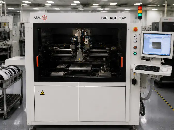
A used ASM SIPLACE CA4 or CA4 V2 should be evaluated as a complete production configuration rather than as a machine model alone. The platform can be arranged for feeder-based SMT placement, direct-wafer flip-chip placement, die attach or a mixed process, but the installed placement heads, wafer systems, feeder tables and conveyor determine which of those functions are actually available.
This distinction is especially important when the machine is intended to replace an existing CA4 line. A replacement may look similar externally while using a different head combination, material-input layout, substrate transport system, software release or set of process modules.
The purchasing decision should therefore connect the exact machine identity with the equipment already used by the factory, the product programs that must be preserved and the material flow required by future production.
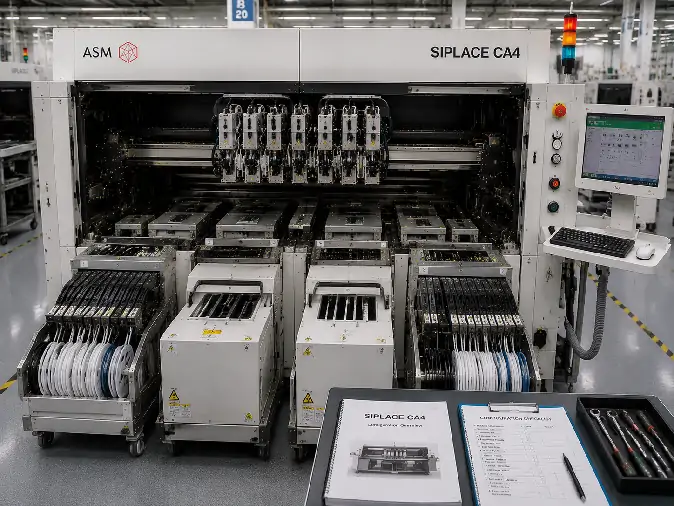
Confirm the Exact CA4 Identity First
The names SIPLACE CA, SIPLACE CA4 and SIPLACE CA4 V2 may appear across brochures, machine records and used-equipment listings. They should not be treated as interchangeable without reviewing the physical machine and its documentation.
Begin by connecting the following records to the same serial number:
| Identity Record | What to Confirm | Why It Matters |
|---|---|---|
| Machine nameplate | Full model designation, serial number, manufacturing information and electrical data | Establishes which physical machine is being quoted and inspected. |
| Software identification | Installed software release, machine configuration and active licenses | Helps distinguish platform generation and available functions. |
| Placement-head labels | Head type, quantity, mounting position and individual identification | The head set changes component range, placement force and process performance. |
| Material-input positions | Installed SIPLACE Wafer Systems, feeder changeover tables and incomplete positions | The four-position layout determines the balance between wafer and feeder supply. |
| Conveyor configuration | Dual-lane, single-lane, wafer-lane or panel-lane arrangement | Substrate dimensions, process flow and published accuracy conditions differ by transport type. |
| Machine history | Previous application, major changes, removed modules and available service records | A machine converted from another process may no longer match its original configuration. |
Photographs should show readable labels and enough surrounding detail to identify where each head, wafer system and feeder table is installed. A model-family brochure or image of another CA4 cannot establish the configuration of the machine being delivered.
The Four Material Positions Define the Production Balance
A central characteristic of the SIPLACE CA architecture is the ability to combine SIPLACE Wafer Systems and feeder changeover tables across four material positions. The installed arrangement determines whether the machine behaves mainly as a high-speed SMT platform, a wafer-fed chip assembly machine or a mixed system.
| Configuration Direction | Material Arrangement | Typical Production Emphasis |
|---|---|---|
| Feeder-dominant | Four feeder changeover tables | High-volume placement of tape-fed SMDs using the applicable head configuration |
| Mixed SMT and wafer | Three feeder tables and one SWS, or two feeder tables and two SWS units | Products combining substantial SMT content with one or more direct-wafer die sources |
| Wafer-dominant | One feeder table and three SWS units | Multi-die products that still require a limited number of feeder-supplied components |
| Direct-wafer focused | Four SIPLACE Wafer Systems | High-volume flip-chip or die-attach production based primarily on wafer-supplied dies |
The number of physical positions is only the first check. Each SWS should be inspected for its wafer exchange hardware, magazine arrangement, wafer stretcher, hoop-ring handling, wafer-map connection, eject system and included tooling.
A feeder-table position should likewise be checked for its mechanical interface, electrical connection, feeder compatibility and included trolleys or feeders. A nominal four-position machine may arrive with an empty, incomplete or disabled station.
Placement Heads Change the Process Window
CA4 V2 configurations may use SIPLACE SpeedStar C&P20 M2 or SIPLACE MultiStar CPP M placement-head technology. The installed head combination affects the component range, process flexibility, placement force and achievable output.
A head suitable for very small, high-volume components does not automatically provide the same handling range or process behavior as a more flexible head. The review should therefore identify:
The head type installed at each gantry position
Whether all four gantries are complete and operational
The component and die range supported by that head set
The available nozzle interfaces and included nozzle inventory
The applicable pickup, placement-force and sensing functions
Recent head maintenance, calibration or replacement records
Official platform data lists benchmark performance of up to 126,500 components per hour for SMD placement with four feeder changeover tables, up to 46,000 components per hour for flip-chip placement with four SWS units and up to 30,000 components per hour for die attach with four SWS units.
These figures describe defined platform configurations. They should not be added together or applied to a mixed machine without considering the installed heads, SWS quantity, conveyor, die-ejection cycle, dipping sequence and product placement pattern.
Wafer and Process Modules Require Separate Verification
A CA4 intended for direct-wafer production needs more than an empty SWS position. The wafer and process modules must support the actual wafer format, die dimensions and joining sequence.
| Process Area | What to Check | Application Consequence |
|---|---|---|
| Wafer format | Supported wafer diameter, frame, stretcher and hoop-ring arrangement | Determines whether the buyer's wafers can be loaded and presented correctly. |
| Wafer maps | Map connection, supported format, software function and recipe records | Controls known-good-die selection and source-position tracking. |
| Die ejection | Ejector hardware, programmable movement, tooling and demonstrated pickup result | Affects die release, damage risk and pickup stability. |
| Die thickness and size | Representative material compared with the installed head, ejector and vision setup | Nominal brochure limits do not confirm stable handling of every die inside the range. |
| Linear Dipping Unit | LDU presence, process plates, material condition, height control and inspection | Determines whether the required flux or dipping sequence can be reproduced. |
| Placement force | Head-dependent programmable force and low-force options | Sensitive dies and substrates may require controlled pickup and placement behavior. |
The official platform supports wafers from 4 to 12 inches and includes automatic wafer exchange and multi-die capability in applicable configurations. The offered machine still has to be checked for the specific stretcher, magazine and frame hardware included in the delivery.
Conveyor Choice Affects More Than Substrate Size
SIPLACE CA configurations may use flexible dual-lane, single-lane, wafer-lane or panel-lane conveyors. The conveyor determines how material enters the machine, which substrate formats are supported and which accuracy conditions apply to the process.
For an existing production line, verify:
Loading and unloading direction
Single- or dual-lane operation
Minimum and maximum substrate format
Substrate thickness and required carrier
Warpage support and clamping arrangement
Synchronous or asynchronous transport
Interface height and connection with adjacent equipment
A replacement machine with the wrong conveyor may require more than a mechanical adjustment. Product programs, carriers, line interfaces and surrounding equipment may all be affected.
Plan the Replacement Around What Must Be Preserved
The most important replacement question is not whether another CA4 can power on in the same factory. It is whether the existing production assets can be transferred without introducing unacceptable process risk or conversion work.
| Replacement Area | What May Need to Be Preserved | What to Compare on the Candidate Machine |
|---|---|---|
| Material supply | Feeder tables, feeders, SWS positions, wafer frames and magazines | Mechanical interfaces, station layout, supported formats and included accessories |
| Placement process | Head type, nozzle set, pickup method, placement force and die sequence | Installed heads, nozzle compatibility, process modules and calibration evidence |
| Product programs | Recipes, component libraries, wafer maps and placement data | Software release, import compatibility, licenses and available backups |
| Substrate handling | Conveyor arrangement, carriers, clamps and line direction | Conveyor type, working range, transport mode and mechanical interfaces |
| Factory communication | Line control, host connection, data export and traceability | Installed interfaces, software functions and communication hardware |
| Facility requirements | Power, compressed air, floor space, access and service clearances | Machine configuration, attached SWS units and final installed dimensions |
| Maintenance support | Spare heads, feeders, boards, drives, tools and technician knowledge | Part compatibility, included spares and future support availability |
A like-for-like replacement is most realistic when the head set, four-position material arrangement, conveyor, software generation and key tooling closely match the existing line.
A candidate machine with a different configuration may still be usable, but the quotation should separate the machine purchase from the additional conversion work. Required changes may include module transfer, software work, new carriers, feeder replacement, program rebuilding, calibration and application testing.
Factories continuing to use legacy SIPLACE feeder systems should also review the ASM Siemens SIPLACE feeder compatibility and replacement guide before assuming that every existing feeder can move directly to the replacement machine.
Evidence to Request for the Candidate Machine
The following evidence can show whether the candidate CA4 matches the proposed replacement plan:
| Evidence | What It Should Show |
|---|---|
| Full machine photographs | Nameplate, gantries, placement heads, all four material positions, conveyor and computers |
| Configuration report | Installed modules, machine options, software release and active functions |
| Head records | Head identity, service work, calibration status and current operation |
| SWS demonstration | Wafer loading, exchange, map reading, ejection, pickup and die recognition |
| SMT demonstration | Feeder communication, component pickup, placement and conveyor transport |
| Process-module test | LDU, inspection, low-force placement or other required functions |
| Program and software records | Available backups, licenses, interfaces and data-transfer capability |
| Delivery list | Heads, SWS units, feeder tables, computers, tooling, manuals, cables and removed parts |
The test does not need to reproduce every historical application, but it should exercise the functions that determine replacement compatibility. A machine that performs only a general dry cycle has not demonstrated wafer handling, feeder communication, process-module operation or product-program transfer.
When the SIPLACE CA4 May Not Be the Right Replacement
Another equipment direction may be more suitable when:
The candidate machine lacks the SWS, head or conveyor configuration required by the existing process.
The cost of transferring modules and rebuilding programs approaches the cost of another platform.
The product now requires component or substrate handling outside the installed configuration.
The joining process requires controlled thermocompression heat, force, dwell time or atmosphere.
The required software interfaces or traceability functions cannot be supported economically.
Essential legacy feeders, heads, boards or service parts are no longer available for the planned operating period.
The factory is changing its material flow sufficiently that preserving the old CA4 architecture no longer provides a real benefit.
The value of a replacement machine comes from maintaining a usable production process, not merely from obtaining another machine with the same model name.
Used ASM SIPLACE CA4 and CA4 V2 FAQ
Are SIPLACE CA, CA4 and CA4 V2 the same machine?
They should not be assumed to be identical. These names may refer to the platform family, a machine configuration or a specific revision. Confirm the nameplate, software release, specification record and installed modules for the machine being offered.
How many wafer systems can a CA4 use?
The SIPLACE CA architecture provides four positions that can be divided between SIPLACE Wafer Systems and feeder changeover tables. A direct-wafer-focused configuration may use up to four SWS units, while mixed configurations use fewer SWS units and retain feeder tables.
Can a CA4 be used only as an SMT placement machine?
Yes. With the appropriate feeder tables, placement heads and software configuration, the platform can perform feeder-based SMD placement without using direct-wafer processing.
What matters most when replacing an existing CA4?
Compare the complete head set, SWS and feeder-table arrangement, conveyor, software, product programs, wafer tooling, feeders and factory interfaces. Matching the model name alone does not confirm a low-risk replacement.
Review the ASM SIPLACE CA4 equipment page for current machine information and inquiry access. For an identified unit, send its nameplate, head layout, four-position material configuration, conveyor details and intended replacement requirements through the All-SMT equipment inquiry page.
Conclusion: A used ASM SIPLACE CA4 or CA4 V2 should be selected by its installed production architecture. Confirm the exact machine identity, map all four material positions, verify the placement heads and conveyor, and compare the software, programs and tooling with the existing line. A successful replacement preserves the process capabilities the factory still needs while making every required conversion visible before the machine is purchased.