1. Overview
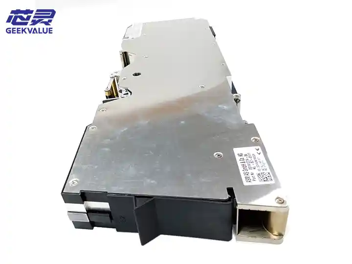
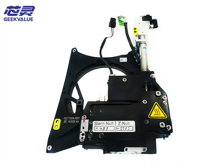
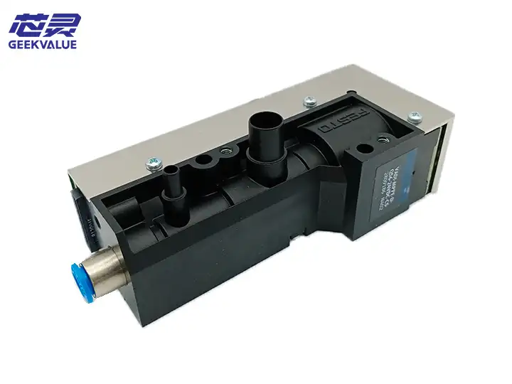
Model: 03106620
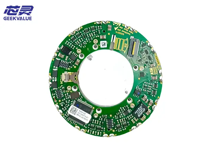
Applicable equipment: ASM SIPLACE CP20P placement head (commonly used in SIPLACE X series and D series placement machines)
Core function: During high-speed placement, electronic components are stably picked up and placed through the vacuum adsorption principle to ensure placement accuracy and efficiency.
2. Core functions
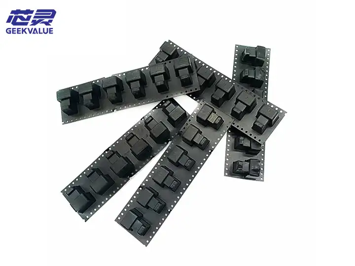
Vacuum adsorption: negative pressure is generated to enable the nozzle to firmly adsorb components (such as resistors, capacitors, ICs, etc.).
Fast response: supports high-speed operation of the placement machine (such as above 30,000 CPH), and the pick-and-place action is completed in milliseconds.
Adjustable pressure: adapts to components of different sizes and weights (such as 0201 small components or large BGA).
Multi-nozzle coordination: some configurations support independent vacuum control of multiple nozzles to improve placement flexibility.
3. Working principle
3.1 Based on Venturi Principle
Compressed air input: high-pressure gas (0.4~0.6 MPa) enters the generator from the air inlet.
High-speed airflow generates negative pressure: When the airflow passes through a narrow channel, the speed increases, forming a low-pressure area in the vacuum chamber, and the component is adsorbed through the nozzle.
Component release: The solenoid valve switches the airflow direction, cuts off the vacuum or blows air briefly, so that the component is separated from the nozzle and accurately mounted.
3.2 Workflow
text
Compressed air → Venturi chamber → Vacuum adsorption → Pick up components → Move to PCB → Release components → Complete mounting
4. Common faults and solutions
4.1 Insufficient vacuum (unstable component pickup or drop)
Possible reasons:
Insufficient compressed air pressure (less than 0.4 MPa).
The nozzle is clogged or worn (aperture deformation).
The vacuum line leaks (aging of the sealing ring or loose joints).
The vacuum generator is internally contaminated (dust, solder paste residue).
Solution:
Check the air source pressure and adjust it to about 0.5 MPa.
Clean or replace the nozzle (make sure there is no blockage).
Check the air line tightness and replace the damaged O-ring or air pipe.
Disassemble the vacuum generator and clean the inside with anhydrous alcohol.
4.2 The vacuum cannot be closed (the component is not released)
Possible reasons:
Solenoid valve failure (coil burnt or valve core stuck).
Abnormal control signal (PLC or I/O module problem).
The internal valve body of the vacuum generator is damaged.
Solution:
Test the solenoid valve on and off and replace the faulty valve body.
Check whether the control signal of the placement machine is output normally.
If the internal valve body is damaged, the entire vacuum generator (03106620) needs to be replaced.
4.3 Abnormal noise (airflow whistling or vibration)
Possible reasons:
The muffler fails or falls off.
The airflow pressure is too high (more than 0.6 MPa).
The internal wear of the vacuum generator (the Venturi tube is deformed).
Solution:
Check whether the muffler is installed in place and replace it if necessary.
Adjust the pressure reducing valve to stabilize the air pressure at 0.4~0.6 MPa.
If the internal structure is damaged, the vacuum generator needs to be replaced.
5. Maintenance methods
5.1 Daily maintenance
Cleaning the suction nozzle and vacuum pipeline:
Wipe the suction nozzle with a dust-free cloth dipped in anhydrous alcohol every day to avoid solder paste or flux residue.
Purge the vacuum pipeline with an air gun to prevent dust accumulation.
Check the air pressure stability:
Ensure that the air source pressure is within the range of 0.5±0.1 MPa.
Calibrate regularly using a barometer.
5.2 Regular maintenance (recommended once every 3 months)
Remove the vacuum generator:
Turn off the air source, unplug the air pipe and electrical interface.
Remove the fixing screws and carefully remove the generator.
Internal cleaning:
Clean the Venturi chamber with an ultrasonic cleaner (or alcohol + soft brush).
Check whether the O-ring is aging and replace it if necessary (refer to the ASM spare part number manual).
Reinstall and test:
Run the vacuum calibration procedure after installation (refer to the SIPLACE software operating guide).
Test the adsorption and release with a standard element to see if it is normal.
5.3 Spare parts replacement recommendations
Recommended original spare parts: ASM 03106620 (to ensure compatibility).
Third-party replacement: Verify that the interface size, vacuum degree and response time match.
6. Technical parameters (reference)
Parameter Specification
Working air pressure 0.4~0.6 MPa
Vacuum degree -60 kPa ~ -80 kPa
Response time ≤10 ms
Interface type G1/8 inch thread or quick-connect connector
Ambient temperature 5~40°C
Service life About 500,000 cycles (depending on maintenance)
7. Precautions
Do not use compressed air containing oil or moisture, otherwise it will cause internal corrosion or component contamination.
When mounting ultra-small components (such as 01005), the vacuum degree needs to be reduced to prevent components from flying.
When the machine is shut down for a long time, the air path should be exhausted and the interface should be sealed to prevent dust from entering.