EN
EN id
id sk
sk sr
sr sv
sv it
it pt
pt bn
bn ms
ms be
be nl
nl fr
fr th
th vi
vi ru
ru ja
ja ko
ko de
de hy
hy az
az bs
bs bg
bg my
my cs
cs da
da dv
dv el
el et
et fil
fil fi
fi ga
ga gl
gl gn
gn he
he hi
hi km
km hr
hr hu
hu is
is kn
kn rw
rw lo
lo lv
lv lt
lt lb
lb lg
lg mi
mi mt
mt ne
ne no
no ny
ny or
or om
om per
per pl
pl ro
ro sa
sa so
so es
es sw
sw ta
ta tr
tr uk
uk ur
ur cy
cy xh
xh
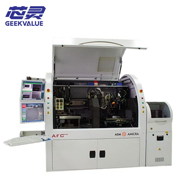
The ASM AMICRA AFC Plus is a modular precision bonding platform associated with die-attach and flip-chip assembly. It sits within ASMPT AMICRA’s ultra-high-precision die-bonding portfolio and is relevant to applications such as micro-optics, MEMS, LED assembly, optoelectronics and advanced semiconductor packaging.
Calling it only a die bonder or only a flip-chip bonder oversimplifies its role. Die bonding describes the broader assembly task, while flip-chip bonding changes the die orientation and introduces different handling, alignment and tooling requirements.
The platform can support several process directions, but the usable capability of an individual machine is created by its installed hardware, software, tooling and qualified process setup. This article explains how those functions relate before project-specific configuration matching begins.
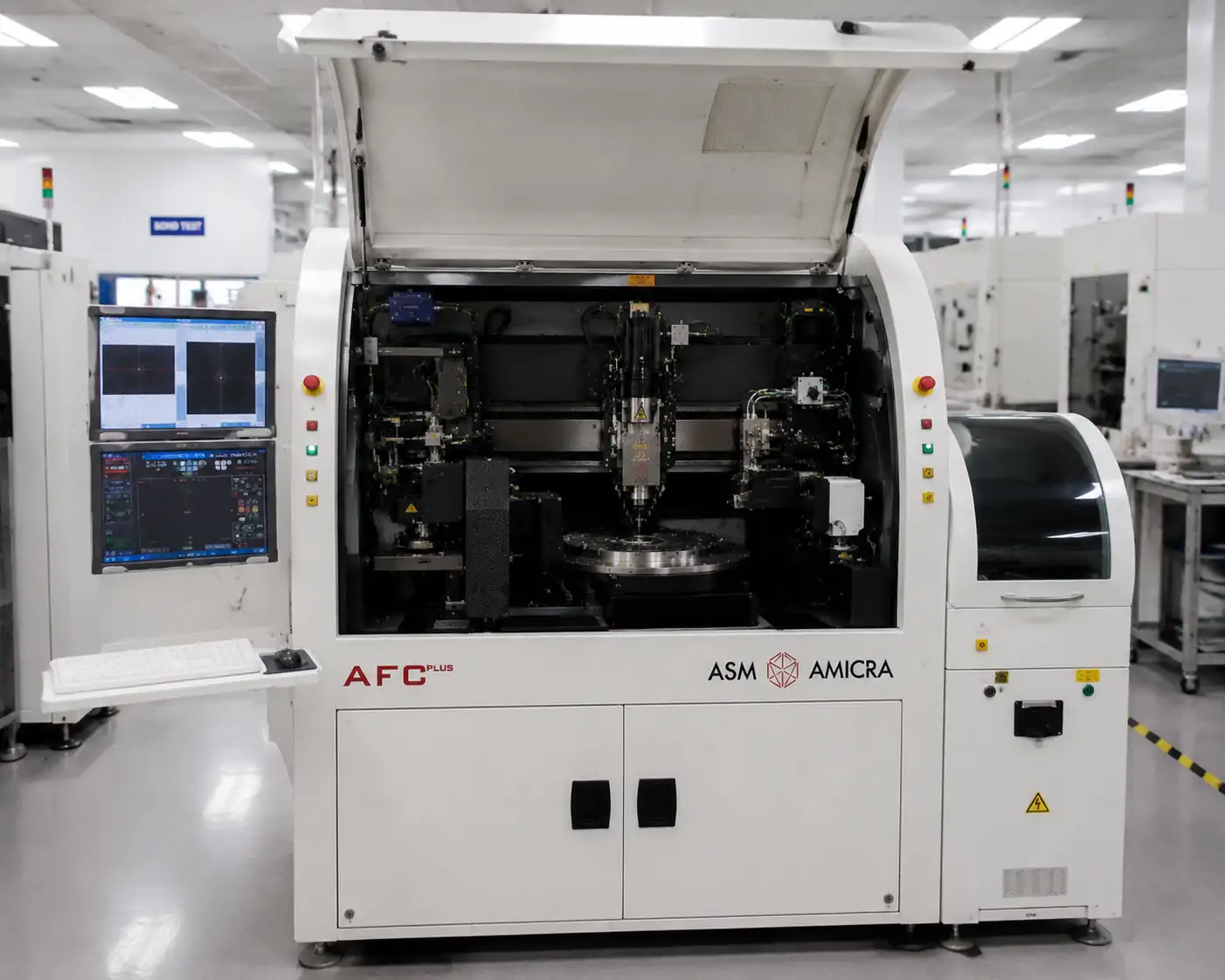
What the ASM AMICRA AFC Plus Is
The AFC Plus is designed to handle, align and bond a semiconductor die or precision component to a target surface under controlled process conditions. Depending on the application, the target may be a substrate, device structure or another assembly surface.
Its modular design allows the bonding route to be built around different die orientations, material systems, handling methods, bonding tools and supporting process functions. Historical ASM AMICRA material describes AFC Plus as a fully automatic die and flip-chip bonding platform, while current ASMPT material continues to place it within the company’s precision bonding portfolio and refers to a modular machine concept with a flip-chip option.
These descriptions establish the platform’s technical direction. They do not define the exact heads, tools, vision functions, material-application modules or software installed on a particular machine.
Die Bonding and Flip-Chip Bonding Serve Different Assembly Routes
Die bonding is the broader process of positioning and joining a die or precision component to a target. In a face-up route, the die remains in the orientation required by the later interconnection or assembly process.
Flip-chip bonding changes that relationship. The active or interconnect side of the die faces the mating surface, so the process must control how the die is picked, turned, supported, aligned and brought into contact with the target.
| Process Aspect | Die-Bonding Direction | Flip-Chip Direction |
|---|---|---|
| Die orientation | The die is placed in the orientation required by the face-up assembly | The active or interconnect side faces the mating surface |
| Target relationship | The die is positioned on a substrate or assembly target | Die features must align directly with corresponding target features |
| Alignment demand | Defined by the die, target references and process tolerance | Often requires close control of relative interconnect alignment |
| Tooling implication | Pickup and bonding tools must suit the die surface and process | Handling may also require die flipping and protection of exposed surfaces |
| Machine configuration | Uses the installed bonding and handling arrangement | Needs the relevant orientation hardware, software, tooling and recipe |
Neither route is universally more advanced. They solve different assembly problems and should be selected according to the die orientation, target structure, bonding material and required joint.
For flip-chip work, the machine needs an appropriate die-handling path, alignment environment, tools, software and demonstrated process setup. The model description alone does not confirm that these elements are present.
How Handling, Alignment and Bonding Work Together
A precision bonding process is created by several connected functions. The die must first be presented in a form that permits safe pickup. The machine then transports it and, where the process requires, changes its orientation before aligning it with the substrate or target.
At a conceptual level, the sequence is:
Present the die → Pick and orient → Align → Apply material or heat where required → Bond → Inspect or record where installed
This is not a fixed AFC Plus program. A face-up die-attach process may follow a different handling route from a flip-chip assembly. An epoxy process may use stamping or dispensing, while a eutectic process places greater emphasis on the material system, thermal control and bonding conditions.
The substrate also needs a stable presentation method. Chucks, fixtures or other supports may be used to hold it in a repeatable position and give the bonding head access to the intended location.
Vision connects the die and target within this process. Cameras, optics and lighting identify reference features, while the alignment method establishes their relative position before bonding. Recognition quality can be influenced by feature contrast, surface condition, calibration, tooling stability and thermal movement.
A model-level accuracy statement cannot describe every project result because alignment performance is produced by the full process environment. Target features, installed optics, tooling, calibration and bonding conditions have to work together.
Software recipes coordinate these physical functions. They may control handling positions, alignment references, material-application stages, motion sequences and other process parameters. The usable bonding route is therefore formed by hardware, tooling, software and calibration acting as one system.
Bonding Materials and Supporting Process Functions
Epoxy Stamping and Dispensing
Epoxy stamping transfers bonding material through a dedicated stamp or tool. It can be useful when the process requires a defined deposit shape or a repeatable amount at a specific location.
Dispensing delivers material through an installed dispensing system and may support different deposit positions, patterns or volumes. Although both methods apply process material, they create different requirements for tooling, control and software.
Stamping requires suitable stamp hardware and tool geometry. Dispensing requires a compatible dispensing system, material path and process control. Their use depends on the intended bonding route rather than the AFC Plus name alone.
Eutectic and Heated Bonding
Eutectic bonding uses a controlled material and thermal process to form the joint. Heat, force, surface condition and process-specific tooling may all influence the result.
Historical official material associates AFC Plus with eutectic and epoxy bonding directions and lists heated tools among the available options. This supports the process relationship, but not one universal temperature, force or bonding sequence. Those values are defined by the selected material system, thermal hardware, bonding head, tooling and qualified recipe.
Wafer Mapping, UV Curing and Post-Bond Inspection
Wafer mapping may support die identification, position selection or other data used by the handling process. Its use relies on the relevant software, interfaces and supported data structure.
UV curing can be incorporated when the bonding material requires ultraviolet exposure after application or placement. It needs compatible curing hardware and a process sequence developed for the selected material.
Post-bond inspection may check die presence, position or other defined results after bonding. Historical official material lists it as an optional AFC Plus function, while the actual inspection scope is determined by the installed optics, software, calibration and acceptance criteria.
Platform Capability and Installed Configuration Are Not the Same
Platform documentation describes process directions that the machine family may support. It does not necessarily describe the configuration of an individual AFC Plus.
A historical brochure may list flip-chip handling, wafer mapping, heated tools or post-bond inspection as options. A current portfolio page may instead emphasize precision positioning and target application areas. Both sources are useful, but they should not be combined into an assumed standard machine.
Each process function needs the correct combination of hardware, software and tooling. Flip-chip operation may require a dedicated orientation mechanism and matching tools. Wafer mapping depends on the corresponding software and data interface. Inspection relies on the installed vision environment, while heated bonding needs appropriate thermal hardware and control.
This is why two AFC Plus machines can serve very different applications. A system configured for micro-optics may have different heads, fixtures, optics and programs from one prepared for MEMS, LED assembly or semiconductor packaging.
Published accuracy and cycle-time figures also need context. Historical values may relate to a dated machine configuration, defined process or specific operating condition, while newer portfolio summaries may describe broader platform positioning.
Die orientation, tooling, alignment method, material handling, thermal steps and installed options can all change the effective process cycle and result. Figures from different sources should retain their original dates and conditions rather than being merged into one universal specification.
Application Areas Do Not Establish Project Compatibility
ASMPT associates the AFC Plus with micro-optics, LED and MEMS assembly, advanced semiconductor packaging and other volume-production applications. These labels indicate markets where precision bonding functions may be relevant.
They do not establish that every product in those markets can run on every AFC Plus. Two photonics or MEMS projects may use different die dimensions, substrate materials, bonding media, orientations, optical references and thermal conditions.
Technical relevance should instead be evaluated from the die, target surface, bonding material and required process route. Input and output handling, tooling, software, inspection, heating and force requirements then determine which machine functions need closer review.
Once those project details are defined, the next step is a project-specific configuration assessment rather than a broader comparison of model descriptions.
Move From Platform Research to Configuration Matching
Platform research has done its job when the intended assembly can be described clearly. A useful review begins with the die dimensions and material, substrate or target, die orientation, bonding method and bonding material.
Alignment references, heating or force requirements, material application, input and output handling, existing tooling and any inspection or curing stage should also be considered. These details determine which bonding head, handling arrangement, optics and supporting modules need to be investigated.
Use the ASM AMICRA AFC Plus configuration page to compare those requirements with the relevant machine functions, or contact the technical team by email or WhatsApp to begin a project review. Die drawings, substrate images, tooling photographs and process documents can be attached after the conversation is opened.
Compatibility, installed options, performance, price and delivery should only be discussed after the project requirements and the relevant machine configuration have been compared.
Frequently Asked Questions About the ASM AMICRA AFC Plus
Is the ASM AMICRA AFC Plus a die bonder or a flip-chip bonder?
It is associated with both die-bonding and flip-chip process directions. Die bonding is the broader assembly task, while usable flip-chip capability requires the appropriate orientation, alignment, tooling, software and process configuration.
What is the difference between die bonding and flip-chip bonding on the AFC Plus?
The main difference is die orientation and its relationship to the target. Flip-chip bonding places the active or interconnect side toward the mating surface, changing the handling, alignment, tooling and bonding sequence.
Does every AFC Plus include flip-chip bonding?
No. Historical official material identifies flip-chip bonding as an option. The relevant hardware, software, tools and process setup must be present on the individual machine.
What do epoxy stamping and dispensing do?
Both transfer process material, but they use different methods. Stamping applies material through a dedicated tool, while dispensing delivers it through an installed dispensing system.
What is eutectic bonding on the AFC Plus?
It is a bonding direction in which a controlled material system, thermal process and process-specific tooling contribute to joint formation. The temperature, force and sequence are defined by the application and installed system.
Can the AFC Plus support photonics, MEMS or advanced-packaging projects?
These are recognized application directions for the platform, but they do not establish compatibility with every product. The die, substrate, material system, orientation, tooling, alignment and required modules must be reviewed for the project.
Conclusion: The ASM AMICRA AFC Plus is a modular precision die and flip-chip bonding platform, but the two bonding directions involve different die orientations, alignment demands and tooling requirements. Vision, material application, heating, wafer mapping, curing and inspection support distinct parts of the process and may require specific installed modules. Platform descriptions can establish technical relevance, while project compatibility requires a configuration review based on the actual die, substrate, bonding method and process conditions.