EN
EN id
id sk
sk sr
sr sv
sv it
it pt
pt bn
bn ms
ms be
be nl
nl fr
fr th
th vi
vi ru
ru ja
ja ko
ko de
de hy
hy az
az bs
bs bg
bg my
my cs
cs da
da dv
dv el
el et
et fil
fil fi
fi ga
ga gl
gl gn
gn he
he hi
hi km
km hr
hr hu
hu is
is kn
kn rw
rw lo
lo lv
lv lt
lt lb
lb lg
lg mi
mi mt
mt ne
ne no
no ny
ny or
or om
om per
per pl
pl ro
ro sa
sa so
so es
es sw
sw ta
ta tr
tr uk
uk ur
ur cy
cy xh
xh
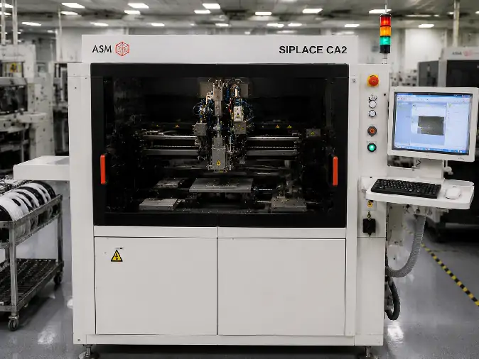
A used ASM SIPLACE CA2 should be evaluated as an individual machine, not only as a model name. Two CA2 systems may differ in their placement heads, wafer equipment, vision package, conveyor, software licenses, process modules and included accessories.
Published platform specifications help define what a properly configured CA2 may support. They do not prove that the machine being offered contains the required hardware, remains calibrated or can reproduce the intended process.
The practical buying task is therefore to connect three things: the product requirement, the installed machine configuration and the evidence produced during inspection and testing. For a broader explanation of the platform, applications and production-line fit, review the ASM SIPLACE CA2 process and configuration guide.
Define the Acceptance Criteria Before Inspecting the Machine
An inspection is only useful when the intended process has already been translated into measurable requirements. A machine may run normally during a general demonstration and still be unsuitable for the buyer’s wafer, die, substrate or traceability flow.
| Project Requirement | Information to Prepare | What the Machine Must Demonstrate |
|---|---|---|
| Die handling | Die length, width, thickness, surface condition and pickup area | Stable ejection, pickup, recognition and placement with representative material |
| Wafer input | Wafer diameter, frame type, map format and number of die types | Compatible loading, wafer exchange, map reading and die selection |
| SMT component supply | Package range, tape widths, feeder quantity and placements per product | Sufficient feeder positions and a workable balance between SMT and wafer modules |
| Maareynta dhulka hoostiisa | Substrate dimensions, thickness, warpage, carrier and loading direction | Stable transport, clamping, indexing and support through the installed conveyor |
| Placement requirement | Required tolerance, critical placement zones and measurement method | Repeatable placement results supported by an agreed measurement process |
| Dipping or material application | Flux or dipping material, transfer depth, die types and process sequence | Operation of the applicable Linear Dipping Unit and inspection functions |
| Raad-raac | Required wafer-map data, die genealogy and factory communication | Recording of the required relationship between source die and final placement position |
| Production output | Placement mix, changeovers, takt-time target and surrounding line constraints | A representative cycle rather than an isolated maximum-speed demonstration |
These criteria should be agreed before the test material and FAT scope are selected. Without them, the final report may describe machine activity without answering whether the machine is suitable for the actual product.
Build a Configuration Record for the Exact CA2
The complete configuration should be linked to the machine serial number. Stock photographs, model-family brochures or module images from another CA2 cannot confirm what will be delivered.
| Aagga Qaabeynta | What to Record | Why It Affects the Purchase |
|---|---|---|
| Aqoonsiga mashiinka | Full designation, serial number, manufacturing record, nameplate and current location | It connects the quotation, inspection evidence and packing list to the same physical machine. |
| CP20 placement heads | Head quantity, labels, visible condition, nozzle interfaces, sensors and available service records | The installed heads affect component handling, speed, accuracy and production stability. |
| Vision and inspection | Cameras, lighting, component sensors, high-resolution options and die-inspection functions | The vision package determines which component features and defects can be recognized. |
| Qalabka Wafer-ka | Multi Wafer Systems, exchange unit, magazines, chuck, ejector, buffer and flip mechanism | Missing wafer modules can remove the direct-wafer functions that created the original buying interest. |
| Material modules | Feeder positions, feeders, tray arrangements, LDU, process plates and related accessories | The material setup must match the product’s balance of wafer-supplied dies and feeder-supplied SMDs. |
| Gaadhida | Single- or dual-lane arrangement, loading direction, supported format, carriers and substrate supports | The installed transport system determines whether the intended substrate can be processed reliably. |
| Software-ka iyo interface-ka | Software release, active licenses, wafer-map support, backups, traceability and factory interfaces | Installed hardware may remain unavailable if its software functions or licenses are missing. |
| Included tooling | Nozzles, frames, chucks, ejector tools, feeders, carriers, cables and service accessories | Missing tooling may delay installation or require additional sourcing after delivery. |
Photographs should show readable labels and enough surrounding machine detail to identify where each module is installed. The configuration record should also note removed, disabled or incomplete items rather than describing only the main machine.
Use Evidence That Shows More Than Basic Machine Motion
A general running video can confirm that the machine powers on, loads its control software and moves its main axes. It cannot by itself confirm wafer compatibility, die recognition, placement quality, active software options or the condition of every process module.
Machine and Module Identification
Request recent photographs of the nameplate, control computer, both placement-head positions, wafer equipment, conveyor, material area and included accessories. The serial information should remain consistent across photographs, test records, quotation and packing documents.
Software and Configuration Records
Review the installed software version, configuration report and active functions. Wafer-map processing, die-level traceability, factory communication and optional inspection features should be demonstrated where they are required by the project.
Service, Alarm and Calibration Information
Available records may reveal placement-head work, camera replacement, conveyor repair, software changes or extended periods of inactivity. Any unresolved alarms, bypassed sensors or disabled modules should be recorded before the purchase is finalized.
A calibration record is most useful when it identifies the machine, date, configuration, measurement method and result. A generic statement that the machine has been calibrated does not establish which functions or accuracy conditions were checked.
Representative Operating Evidence
The demonstration should show the process functions that matter to the buyer. Wafer exchange, map reading, die ejection, pickup, recognition, dipping, placement, transport and data recording are more informative than repeated head movement without material.
Design the FAT Around the Intended Product
The Factory Acceptance Test is the strongest opportunity to connect the offered machine with the buyer’s production requirement. It should follow the actual material path as closely as the available wafers, dies, substrates and process media allow.
| FAT Stage | Test Activity | Evidence to Retain |
|---|---|---|
| Startup and system status | Power on the machine, load the software and review alarms and module status. | Startup video, software version, configuration screen and alarm record |
| Wafer loading and exchange | Load the applicable frame and run the required wafer-selection or exchange sequence. | Wafer identification, frame fit, exchange operation and magazine arrangement |
| Wafer-map processing | Load or read the applicable map and select the required die locations. | Map screen, source position, die-status handling and recipe information |
| Ejection and pickup | Operate the ejector, buffer and pickup sequence with representative dies. | Pickup video, failed-pick behavior, die condition and alarm response |
| Aragtida iyo jihaynta | Recognize the die, verify orientation and exercise the required inspection functions. | Camera image, recognition result, rejection behavior and inspection output |
| Dipping process | Run the LDU where the intended process requires flux or another dipping medium. | Material condition, dipping sequence, transfer consistency and inspection result |
| Placement and measurement | Place representative dies or components on the intended substrate or a qualified test coupon. | Placement program, measured result, repeatability data and test conditions |
| Substrate transport | Run loading, clamping, indexing and unloading through the installed conveyor. | Substrate dimensions, carrier details, transport video and observed instability |
| Traceability and data | Record the relationship between source material, machine process and final placement location. | Machine log, wafer-map record, substrate identification and exported data |
| Repeat cycle | Run enough repeated operations to expose intermittent pickup, recognition or transport problems. | Cycle count, alarms, rejected parts, interruptions and operator actions |
The acceptance limits should be defined before testing. Terms such as “running normally,” “good accuracy” or “fully tested” are too broad when the project depends on a specific placement result, material sequence or software function.
Testing Without the Buyer’s Production Material
Representative material can still provide useful evidence when the real wafer or substrate is unavailable. The FAT report should state which dimensions, surfaces and process conditions were represented, which functions were demonstrated and which application risks remain unresolved.
A dry cycle can verify basic movement, conveyor operation and some alarm functions. It should not be treated as proof of die pickup stability, vision performance, dipping quality, placement accuracy or production readiness.
Confirm the Delivery Scope Before Shipment
The delivery list should be reviewed together with the FAT record. A machine can pass its demonstration and still arrive incomplete if tooling, computers, process modules or transport parts are omitted from the final packing scope.
Confirm whether the shipment includes:
The identified machine and all installed covers and safety components
Both placement heads and the nozzles required by the agreed test
Wafer magazines, frames, chucks, ejector tooling and exchange accessories
Feeders, feeder tables, trays and material-handling accessories stated in the quotation
LDU components, process plates and related inspection hardware where applicable
Substrate carriers, conveyor accessories and support tooling
Control computers, monitors, cables, interface devices and peripheral hardware
Software backups, license information, machine data and available manuals
Calibration tools, reference items and service accessories included in the agreement
Spare parts, known-defect records and items removed for transport
Before export packing, sensitive assemblies and moving modules should be secured according to the agreed transport plan. Removed parts should be labelled so that the receiving team can identify their machine position during installation.
When the SIPLACE CA2 May Not Be the Right Fit
A CA2 should not be approved simply because the product contains bare dies or uses a flip-chip orientation. Another equipment type may be more suitable when:
Habka isku-darka wuxuu u baahan yahay kulayl heerkulbeeg ah oo la xakameeyey, xoog, waqti deggan ama jawi.
The die or component dimensions fall outside the installed handling range.
The process requires dispensing, curing or bonding functions that are not installed.
The feeder-intensive SMT workload exceeds the practical material capacity of the selected CA2 setup.
The substrate cannot be supported by the installed conveyor, carrier or accuracy area.
The required wafer, vision, dipping or software modules are missing and cannot be supplied economically.
The intended volume does not justify an integrated high-speed wafer-placement platform.
Projects requiring a dedicated bonding process can also be compared with the available flip chip bonder equipment. The machine category should follow the required joining method, not only the presence of a face-down die.
Used ASM SIPLACE CA2 FAQ
Is a general running video enough to approve a used CA2?
No. It can confirm basic startup and motion, but it does not prove wafer compatibility, die recognition, dipping, placement accuracy, traceability or the condition of every installed module.
Can two used CA2 machines have different production capabilities?
Yes. Their wafer equipment, vision package, conveyor, software licenses, material modules and included tooling may differ. The complete configuration should be tied to the serial number of the machine being offered.
What is the most valuable CA2 FAT evidence?
The strongest evidence is a connected process sequence showing material loading, die selection, ejection, pickup, recognition, optional dipping, placement, substrate transport and the corresponding measurement or traceability results.
What should be included in a used CA2 quotation?
The quotation should identify the exact machine, installed modules, known condition, agreed test scope, included tooling, software and documentation, unresolved defects, packing responsibility and final delivery list.
Dib u eegASM SIPLACE CA2 equipment page for machine information and inquiry access. To discuss an identified unit, send its nameplate, configuration photographs and intended process through the Bogga baaritaanka qalabka oo dhan-SMT. The available evidence and FAT scope can then be discussed against the project requirements.
Gunaanad: A used ASM SIPLACE CA2 should be purchased as a verified machine configuration, not as a brochure specification. Define the acceptance criteria first, document the exact installed hardware and software, test the functions that matter to the product, and connect the FAT result to a complete delivery list. This is the clearest way to confirm that the capability demonstrated before shipment is the capability the buyer expects to receive.