EN
EN id
id sk
sk sr
sr sv
sv it
it pt
pt bn
bn ms
ms be
be nl
nl fr
fr th
th vi
vi ru
ru ja
ja ko
ko de
de hy
hy az
az bs
bs bg
bg my
my cs
cs da
da dv
dv el
el et
et fil
fil fi
fi ga
ga gl
gl gn
gn he
he hi
hi km
km hr
hr hu
hu is
is kn
kn rw
rw lo
lo lv
lv lt
lt lb
lb lg
lg mi
mi mt
mt ne
ne no
no ny
ny or
or om
om per
per pl
pl ro
ro sa
sa so
so es
es sw
sw ta
ta tr
tr uk
uk ur
ur cy
cy xh
xh
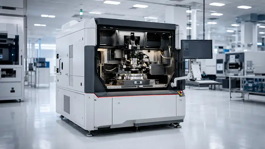
An ASM AD838 die bonder should be selected by its material flow and installed process configuration, not by the AD838 name alone. A machine may have suitable placement hardware but still lack the wafer format, carrier tooling, bond head, nozzle set, dispensing module, vision package or substrate fixture needed for the target application.
For LED, photonics, optoelectronics and other precision die attach projects, the real equipment question is practical: how does the die enter the machine, how is it picked, how is adhesive or process material prepared, how is alignment verified, what carrier or substrate receives the die, and what tooling is available to support the full sequence?
This ASM AD838 die bonder configuration guide explains the key areas that should be reviewed before selecting, purchasing, refurbishing or qualifying an AD838 die bonding machine.
In Brief: What Determines ASM AD838 Die Bonder Capability?
The practical capability of an ASM AD838 die bonder depends on the exact machine version and installed configuration. Key areas include wafer handling, die source method, carrier or substrate handling, bond head setup, nozzle and eject tooling, dispensing or stamping modules, vision system, alignment method, automation hardware, controller and software status.
Wafer size alone does not confirm the full die source capability.
Carrier tools and substrate fixtures can determine whether the machine fits the product.
Bond head and nozzle setup must match die dimensions, die condition and placement method.
Vision performance must be reviewed against real alignment marks and substrate features.
Tooling availability can determine qualification speed more than the machine cabinet itself.
Why Material Flow Should Be Defined Before Selecting an ASM AD838 Machine
Every die bonding project has a physical flow. The die begins at a wafer, tray, waffle pack, Gel-Pak®, carrier or other presentation method. It is picked with a defined tool, may pass through a dispensing or stamping step, is aligned through a camera or reference system, and is placed onto a substrate, leadframe, carrier, fixture or package component.
The machine configuration must support every important step in that flow. A gap in any one area can stop the project from moving into qualification.
Configuration principle: Match the AD838 machine to the complete die attach sequence, not only to the die size or the platform family.
1. Identify the Exact AD838 Platform Before Reviewing Configuration
Before reviewing hardware, identify the exact machine designation. Original AD838 systems, later AD838L machines, AD838L-Plus and AD838L-G2 systems should not be assumed to have the same published features, material handling or process options.
Ask for the nameplate image, serial number, full model name and machine configuration list. This helps prevent a common mistake: applying the published capability of one AD838-family variant to another offered machine.
2. Define the Die Source and Wafer Handling Route
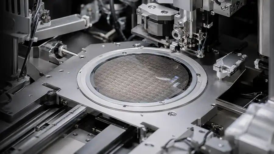
Wafer handling should be reviewed from the first loading point through die pickup. Confirm wafer diameter, wafer frame or ring style, die presentation, ring expander requirement, wafer loader configuration and any automatic handling modules included with the machine.
For fragile, thin, small or application-specific die, also review how the die is released, supported and transferred to the pickup point. Die condition, backside treatment, sawing method and wafer mounting material can influence the required pickup strategy.
Questions to Ask
What wafer diameter and frame style is the machine configured to handle?
Is a ring expander, wafer loader or wafer handling module included?
What die thickness and die size range was the machine previously used for?
What pickup method and eject mechanism are installed?
Can the supplier demonstrate handling using representative material?
3. Review Carrier, Substrate and Fixture Handling
After pickup, the die must be placed onto a receiving surface. This may be a ceramic substrate, metal carrier, LED package component, photonics submount, leadframe, strip, boat, optical component holder or custom fixture.
The receiving side of the process often determines whether a used machine can be qualified quickly. A machine may have a capable bond head but lack the correct fixture plate, locating method, substrate stage, heating plate or transfer path for the target product.
Request details about included carrier tools, substrate holders, fixture plates, heater stages, locating pins, clamps and custom hardware. Compare these against the exact geometry and material of the intended receiving component.
4. Match the Bond Head and Tool Interface to the Die
Bond head configuration should be reviewed against the die size, thickness, pickup surface, fragility, material route and required placement orientation. A tool that works well for one LED die or photonics component may not be appropriate for another die shape or substrate design.
Confirm the installed tool holder interface, nozzles, collets, eject tools, pickup tools and calibration references. Where the project requires heating, rotation, controlled placement force or specialized process motion, verify that the physical configuration supports those needs.
5. Confirm the Material Preparation Route
Die attachment often requires material preparation before placement. Depending on the application, the process may involve epoxy dispensing, stamping, adhesive transfer, fluxing, dipping, heating, UV-related steps or another material route.
Do not assume that a machine can support the target material because it has a dispensing or stamping module installed. Confirm the actual hardware, fluid path, process condition, material compatibility, tool state and the intended cycle sequence.
Material Preparation Review Checklist
Dispensing, stamping or material-transfer module included
Condition of valves, syringes, pumps, nozzles and dispense tools
Required material viscosity, volume or pattern
Heated stage, preheat or thermal process requirement
Cleaning and maintenance condition of material-contact parts
Compatibility with the intended adhesive, flux or process medium
6. Verify Vision and Alignment Against the Actual Product
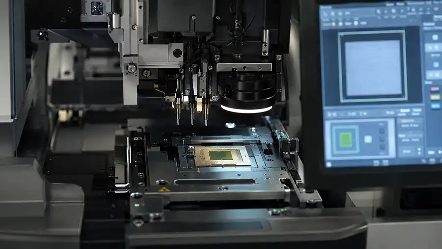
Vision systems should be evaluated against the real die, substrate and reference features used in production. Camera condition, optics, illumination, field of view, alignment logic and calibration can all affect the practical result.
A camera visible in a machine photo is not enough. The machine should demonstrate reference recognition and alignment behavior using representative material, a process sample or a defined optical target.
For photonics or optoelectronics work, alignment may be especially sensitive to substrate geometry, package features, die orientation and application-specific visual references. The inspection approach should be agreed before purchase.
7. Understand Tooling as a Core Part of the Machine
Tooling is not an optional accessory. Nozzles, collets, eject tools, carrier plates, fixture inserts, calibration blocks and substrate holders can determine whether the machine is usable for the target package.
Before purchase, request an itemized tooling inventory with photos, quantities, part references where available and known process use. Then classify each item as:
Compatible with the new product
Potentially adaptable
Requires engineering confirmation
Not relevant to the intended process
Missing and requiring new design or sourcing
8. Check Automation and Changeover Requirements
Automation needs can vary substantially between prototype work, low-volume assembly and high-volume production. Review whether the machine includes automatic material loading, unloading, magazine handling, feeder support, wafer transfer, tool changing or product-changeover features relevant to the project.
For mixed-product environments, evaluate the time needed for nozzle changes, fixture changes, carrier setup, recipe loading, camera adjustment and process verification. A machine may have high theoretical placement potential but still be inefficient for frequent product changes.
9. Verify Controller, Software and Recipe Readiness
Machine software should be treated as part of the production configuration. Confirm controller condition, industrial PC, software version, enabled options, vision settings, available backups, recipes, parameter files and technical documentation.
When replacing an existing machine, determine whether current recipes, tools and operator workflows can be transferred. This is especially important where the process already depends on established die positions, dispensing patterns, carrier locations or visual alignment routines.
ASM AD838 Configuration Matrix
| Configuration Area | What to Verify | Why It Matters |
|---|---|---|
| Machine Identity | Exact AD838-family designation, serial number, generation and physical configuration. | Prevents applying the wrong published capability to the offered machine. |
| Wafer Handling | Wafer size, frame, ring expander, loader, pickup method and eject setup. | Determines whether die can be presented and released correctly. |
| Carrier / Substrate | Fixture plates, holder style, heating need, locating method and physical dimensions. | Determines whether the receiving component can be positioned and supported correctly. |
| Bond Head | Tool interface, pickup method, force-related setup, heating, rotation and motion condition. | Determines whether die can be picked and placed safely. |
| Material Module | Dispensing, stamping, adhesive route, fluxing, heating or process preparation hardware. | Determines whether the full die attach route can be completed. |
| Vision | Camera, optics, illumination, calibration, alignment references and software. | Determines whether the required alignment method can be validated. |
| Tooling | Nozzles, eject tools, fixtures, carrier plates and calibration references. | Often determines project readiness more than the main machine frame. |
| Software | Controller, PC, options, backups, recipes, recovery media and documentation. | Determines installation, troubleshooting and long-term support risk. |
Common ASM AD838 Configuration Mistakes
Mistake 1: Selecting by Wafer Size Only
Wafer size is important, but it does not confirm die presentation, eject method, carrier handling, substrate tooling, bond head configuration or vision capability.
Mistake 2: Assuming Included Tooling Fits the New Product
Original tools may have been designed for a different die, substrate, package geometry, material route or process sequence. Tooling compatibility must be checked against the new application.
Mistake 3: Ignoring the Receiving Substrate
Many projects focus on die pickup but underestimate substrate or carrier handling. Missing fixture hardware can stop qualification even when the die source side is ready.
Mistake 4: Treating Cameras as Proof of Alignment Capability
A machine may include cameras but still require different optics, illumination, software settings, calibration tools or alignment logic for the target package.
Mistake 5: Leaving Software and Recipe Planning Until After Delivery
Controller recovery, backups, option files, recipe access and documentation should be verified before shipment. These items can be difficult to reconstruct after installation.
What to Request Before Approving an ASM AD838 Quotation
Machine nameplate image and serial number
Current high-resolution images of process area and handling modules
Written list of installed wafer, carrier and substrate handling hardware
Bond head, nozzle, eject tool and fixture inventory
Dispensing, stamping or material preparation module details
Vision camera, optics and illumination information
Controller, PC, software, option and backup status
Refurbishment or maintenance information where available
FAT proposal and functional demonstration scope
Packing, installation and support terms
Final Recommendation: Match the Full Process Route
An ASM AD838 die bonder can be a strong platform option when the actual machine configuration matches the full production process. The correct review begins with the die source, carrier or substrate, material route, bond head, tooling, vision strategy and software environment.
Before approving an AD838 quotation, verify that every important link in the process chain is covered. This helps prevent a common equipment-purchasing mistake: selecting a suitable machine family with an unsuitable installed configuration.
Related ASM Die Bonder Resources
Frequently Asked Questions About ASM AD838 Configuration
Are ASM AD838, AD838L and AD838L-G2 the same machine?
No. They are related model designations but should not be assumed to have identical configurations, material handling, tooling, vision systems or published process capability. Always verify the exact offered machine.
What is the most important AD838 configuration check?
The most important check is whether the full process chain matches the application: die source, wafer handling, carrier or substrate handling, bond head, tooling, material route, vision and software.
Why is carrier handling important in die bonding?
Carrier and substrate handling determine how the receiving component is held, positioned, heated and transferred. Missing or incompatible fixtures can prevent process qualification.
Can an ASM AD838 use different nozzle and tool sets?
Tool compatibility depends on the installed head, tool interface and process setup. Buyers should request an itemized tool list and verify suitability for the intended die and substrate.
What should be checked for AD838 vision alignment?
Check installed camera hardware, optics, illumination, field of view, calibration condition, alignment software and performance against representative die and substrate features.
Can a used AD838 die bonder support a new product?
It may be possible, but suitability depends on whether the required handling modules, tools, fixtures, material process hardware, vision setup and software can support the new product route.
What information is needed for an AD838 configuration review?
Provide machine photos, serial number, die dimensions, wafer or tray format, substrate details, material route, target output, tooling inventory and intended process flow.
Need Help Reviewing an ASM AD838 Process Configuration?
Share the available machine configuration, die size, wafer or carrier format, substrate drawing, material route, tooling details and target production requirements. A useful AD838 review begins with the complete process route rather than the platform name alone.