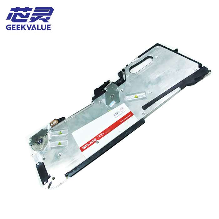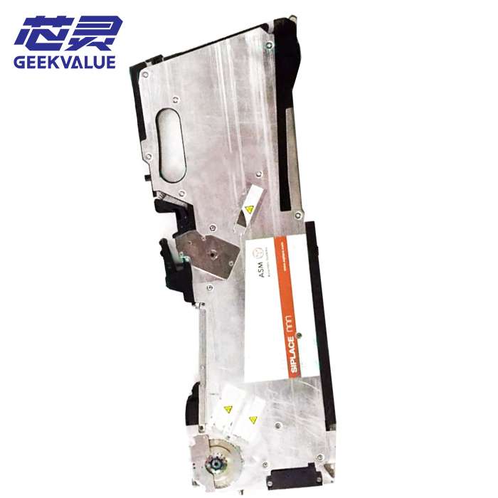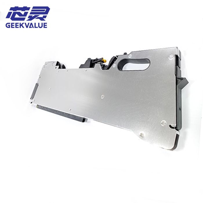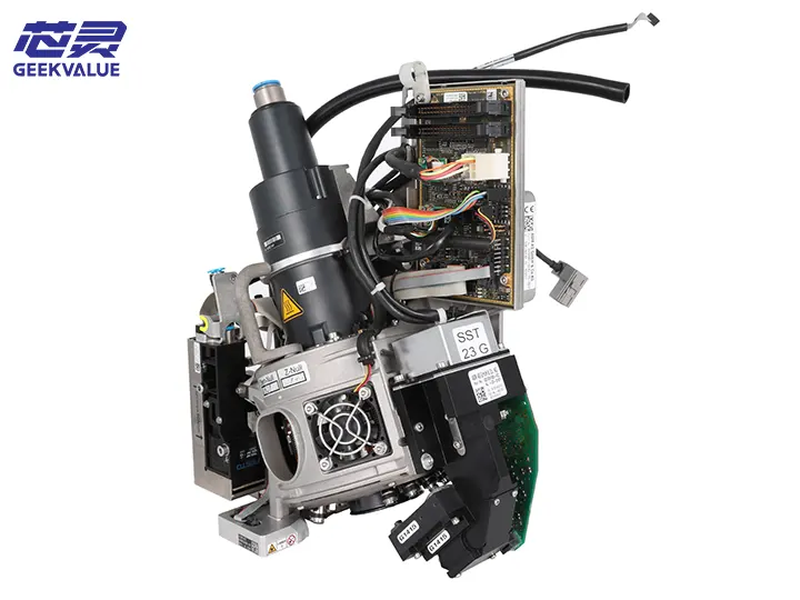
The SIPLACE CP14 work head is a core placement module designed by ASM Assembly Systems (formerly Siemens Electronic Assembly Systems) for high-speed and high-precision placement machines, and is a key component of the SIPLACE X series placement machines. The work head is optimized for high-volume, high-mix electronic manufacturing environments and is suitable for ultra-high-speed and precise placement of 01005 to large IC components (such as 0402, 0603, QFN, POP, etc.).
2. Technical background and market positioning
Development background: To meet the high-density placement requirements of micro components (01005) and special-shaped components in industries such as 5G and automotive electronics
Market positioning: Mid-to-high-end SMT production lines, balancing speed and precision (the theoretical speed of the CP14 work head can reach 156,000 CPH)
Generational relationship: CP14 is an upgraded version of CP12, and the main improvements include:
The nozzle rod is 30% lighter
The response speed of the vacuum system is increased by 20%
Added component surface scanning function
3. Detailed explanation of mechanical structure
1. Core mechanical system
Subsystem Technical features
Multi-axis drive system uses linear motor + magnetic suspension guide technology (patent DE102015216789), Z-axis repeatability ±5μm
Placement head matrix 16 nozzles are independently controlled, and each nozzle is equipped with an independent θ-axis rotation (resolution 0.01°)
Vibration reduction mechanism Three-level vibration reduction design (active electromagnetic damping + passive rubber buffer + air spring)
Quick module replacement Modular design, single work head replacement time <90 seconds (including calibration)
2. Motion control system
X/Y axis: linear motor drive, maximum acceleration 3G
Z axis: voice coil motor drive, pressure control range 0.1-5N (programmable 0.01N step)
θ axis: direct drive motor (DDM), speed 3000rpm
IV. Electronics and sensor system
1. Intelligent sensor network
Sensor type Technical parameters Function
3D laser altimeter Measuring range 0-10mm, resolution 1μm Component coplanarity detection, PCB warpage compensation
High frame rate vision system 2000fps CMOS, 5μm optical resolution Real-time component alignment and defect detection
Matrix vacuum sensor 16 channels independent monitoring, response time <1ms Pickup success rate monitoring and predictive maintenance
Temperature monitoring module 8-point temperature measurement, accuracy ±0.5℃ Thermal deformation compensation and overheating protection
2. Control architecture
Main controller: Xilinx Zynq UltraScale+ MPSoC
Real-time communication: TSN (Time Sensitive Network), cycle time 62.5μs
Safety system: SIL3 safety brake, dual redundant encoder verification
V. Performance parameters
1. Basic specifications
Parameters Index
Applicable component range 01005 (0.4×0.2mm)~30×30mm (including 0.3mm pitch CSP)
Theoretical mounting speed 156,000CPH (IPC9850 standard)
Mounting accuracy ±25μm@3σ (Cpk≥1.67)
Minimum component spacing 0.15mm (special nozzle required)
Weight 4.2kg (including standard nozzle set)
2. Environmental requirements
Parameters Requirements
Working temperature 23±2℃ (constant temperature workshop required)
Humidity range 40-60%RH (no condensation)
Compressed air 6bar±0.2bar, ISO8573-1 Class 2 standard
VI. Core technology innovation
1. Dynamic Accuracy Compensation System (DACS)
Real-time compensation factors:
Mechanical thermal deformation (through temperature sensor network)
Motion inertia (based on acceleration feedforward control)
PCB deformation (3D scanning data feedback)
2. Intelligent placement strategy
Pressure adaptive control:
Soft landing technology (<0.1N contact force)
Solder paste deformation monitoring (through laser displacement sensor)
Component handling algorithm:
Asymmetric component anti-flip control
Micro component anti-splash algorithm
VII. Maintenance system
1. Three-level maintenance plan
Cycle Item Technical points
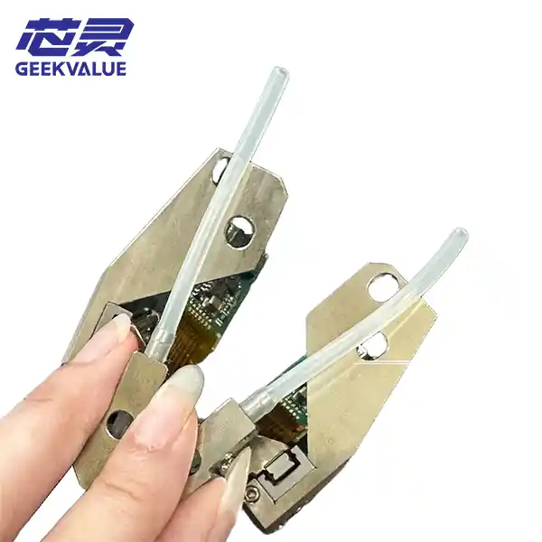
Daily Nozzle cleaning inspection Use a special cleaning pen (P/N: SIPLACE 488-223) to clean the inner wall of the nozzle
Weekly inspection Vacuum system inspection Test the vacuum establishment time of 16 channels (standard value <50ms)
Monthly maintenance Lubrication of moving parts Use special grease (Klüberplex BEM 41-132), dosage 0.2ml/guide rail
Annual inspection Comprehensive calibration Includes:
• Optical system focal length calibration
• Encoder phase compensation
• Force sensor zero point calibration
2. Predictive maintenance function
Health index monitoring:
Nozzle wear (based on vacuum waveform analysis)
Bearing life prediction (vibration spectrum diagnosis)
Intelligent alarm system:
Early fault warning (such as E710: Z-axis harmonic abnormality)
Maintenance suggestion push (through ASM Remote Smart Factory)
8. Typical fault diagnosis
1. Mechanical fault
Code Phenomenon Root cause analysis Solution
E201 Z-axis servo overload Voice coil motor heat dissipation is poor Clean the heat dissipation channel and check the cooling fan
E315 θ-axis positioning deviation Encoder signal is interfered Check the shielding wire and redo the grounding
2. Vacuum system failure
Code Phenomenon Root cause analysis Solution
E407 Multi-channel vacuum failure Distribution valve diaphragm is damaged Replace the valve group (P/N: SIPLACE 577-991)
E412 Vacuum response delay Partial blockage of the pipeline Use 0.3mm needle to clean
3. Vision system failure
Code Phenomenon Root cause analysis Solution
E521 Image blur Lens group pollution or LED attenuation Professional optical cleaning, measure the light source intensity
E533 Abnormal calibration data Calibration board positioning deviation Re-execute Vision Calibration Wizard
IX. Upgrade and selection
1. Function expansion options
Option code Function description
OPX-014-001 Ultra-precision placement kit (including nano-level nozzle, accuracy improved to ±15μm)
OPX-014-003 high temperature version (supports 85℃ environment, including special lubrication system)
OPX-014-005 anti-static kit (ESD<10V, suitable for RF components)
2. Intelligent upgrade path
ASM Smart Reponse: AI-based placement parameter self-optimization
Digital Twin Kit: Workhead digital twin modeling toolkit
X. Application case
Automotive electronics production line configuration plan:
Equipment combination: 4×SIPLACE X4s (each equipped with 2 CP14 work heads)
Typical components:
01005 resistors (60% 0402)
QFN-56 (0.4mm pitch)
Special-shaped connectors (up to 15mm)
Measured performance:
Comprehensive OEE: 92.3%
Mean failure interval: 1,750 hours
XI. Technology development trend
Lighter design: Carbon fiber nozzle rod (50% weight reduction)
Multi-physics field coupling control:
Vibration-heat-stress collaborative optimization
Quantum sensing application:
Nanoscale position measurement (prototype stage)
This work head represents the current advanced level of SMT placement technology. It achieves a perfect balance between speed and accuracy through deep technology integration and is the preferred solution for high-end electronic manufacturing.