EN
EN id
id sk
sk sr
sr sv
sv it
it pt
pt bn
bn ms
ms be
be nl
nl fr
fr th
th vi
vi ru
ru ja
ja ko
ko de
de hy
hy az
az bs
bs bg
bg my
my cs
cs da
da dv
dv el
el et
et fil
fil fi
fi ga
ga gl
gl gn
gn he
he hi
hi km
km hr
hr hu
hu is
is kn
kn rw
rw lo
lo lv
lv lt
lt lb
lb lg
lg mi
mi mt
mt ne
ne no
no ny
ny or
or om
om per
per pl
pl ro
ro sa
sa so
so es
es sw
sw ta
ta tr
tr uk
uk ur
ur cy
cy xh
xh
A BESI flip chip bonder should be selected by process route, not by machine name alone. A platform that is suitable for high-speed mass reflow flip chip may not be configured for a multi-chip assembly sequence, a fan-out process, a special substrate format or an application that requires different tooling, vision, handling and inspection conditions.
Buyers searching for a BESI flip chip bonder, DATACON flip chip bonder, BESI flip chip machine, flip chip mounter or DATACON machine often start with a platform name. However, the more useful starting point is the actual package route: what die must be flipped, how it will be presented, what substrate or carrier is used, how alignment is verified, what material process is required, and what production target must be achieved.
This guide explains how to compare BESI flip chip bonder directions for mass reflow, multi-chip and fan-out packaging workflows, and which machine configuration questions should be answered before approving equipment for purchase, refurbishment or process qualification.
In Brief: How Should a BESI Flip Chip Bonder Be Selected?
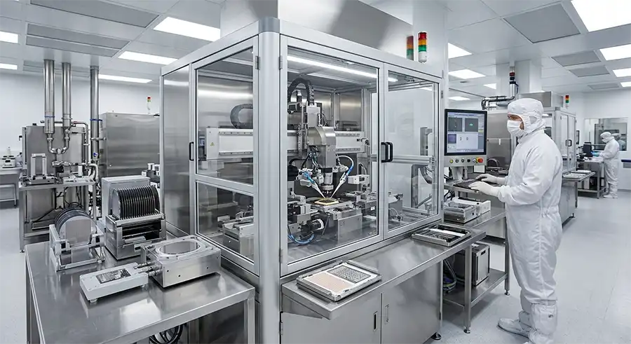
Select a BESI flip chip bonder by first defining the package route, die format, bump or interconnect structure, substrate type, material process, handling sequence, vision requirement, placement target and expected throughput. Then verify that the offered DATACON or Esec configuration includes the required bond heads, flip tools, wafer handling, substrate modules, tooling, cameras, inspection functions, software and support scope.
Mass reflow flip chip projects usually prioritize production speed, repeatable material flow and full process control.
Multi-chip flip chip projects often require more flexible handling, multiple process steps and application-specific tooling.
Fan-out and wafer-level packaging routes require careful review of substrate handling, alignment strategy, process sequence and inspection conditions.
Two systems with the same platform family can still differ substantially in installed tooling and usable process capability.
Why Flip Chip Bonder Selection Starts With the Process Route
Flip chip assembly is not one fixed production task. The required equipment configuration changes depending on whether the process is built around mass reflow, chip-to-substrate placement, multi-chip integration, fan-out packaging, panel or wafer handling, high-density interconnects or a specialized production flow.
A platform may be capable of high placement speed, but that does not confirm it has the required die flipping method, flux or material preparation module, carrier handling, vision field of view, post-bond inspection route, process tooling or recovery sequence.
Selection principle: The right flip chip bonder is the machine that can complete the required process chain with the correct tools, material flow, vision strategy and validation method.
Three Flip Chip Production Routes That Require Different Equipment Decisions
1. Mass Reflow Flip Chip Production
Mass reflow flip chip routes are often evaluated where high-volume chip-to-substrate assembly, repeatable material flow and production efficiency are key requirements. In this environment, the machine configuration must support the intended die presentation, substrate handling, flip operation, material preparation, placement sequence and process-control strategy.
When evaluating a BESI DATACON flip chip bonder for this route, buyers should focus on the actual installed production hardware rather than only a throughput figure from a platform brochure.
Wafer and substrate handling configuration
Flip tool and die presentation method
Fluxing, dipping or process-material route where applicable
Vision alignment and substrate reference recognition
Post-bond inspection or process-control functions
Tooling inventory and device-changeover requirements
2. Multi-Chip Flip Chip Assembly
Multi-chip assembly can introduce more complex process sequencing. One product may require different die sizes, multiple tools, different pick locations, varied placement sequences, specialized carrier handling or multiple material steps within a single production route.
For this type of project, flexibility can matter as much as speed. The buyer should confirm how many working heads are installed, which tools can be used, how the machine handles die changes, whether the process sequence can be configured and what material modules are included.
A system that performs one high-speed repeated placement task well may not be the right configuration for a multi-chip route with different die types and a more complex sequence.
3. Fan-Out and Wafer-Level Packaging
Fan-out and wafer-level packaging workflows should be reviewed against the actual package design, carrier or substrate route, placement reference strategy, die handling method, process materials and inspection requirements. These projects may place more emphasis on alignment control, substrate stability, process sequencing and yield validation.
Before selecting a platform, clarify whether the process requires face-down placement, face-up placement, multi-chip assembly, panel or wafer handling, specialized carriers, advanced inspection or application-specific fixtures.
Do not assume that a machine advertised for advanced packaging is automatically ready for a particular fan-out process. The installed module set, tooling and process flow must be verified against the production requirement.
Mass Reflow vs Multi-Chip vs Fan-Out: Equipment Comparison Framework
| Selection Area | Mass Reflow Flip Chip | Multi-Chip Flip Chip | Fan-Out / Wafer-Level Packaging |
|---|---|---|---|
| Primary Focus | Production speed, repeatable material flow and process control. | Flexible process sequence, multiple die types and application-specific tooling. | Alignment strategy, carrier stability, packaging flow and yield control. |
| Handling Review | Wafer, substrate, strip or carrier flow for repeated high-volume operation. | Multiple die sources, tool changes, carrier changes and mixed material handling. | Carrier, panel, wafer, reconstituted substrate or package-specific handling route. |
| Tooling Review | Flip tools, nozzles, material-preparation hardware and production fixtures. | Multiple pickup tools, die-specific nozzles, custom fixtures and sequence-related accessories. | Application-specific tools, carrier fixtures, alignment references and inspection-related hardware. |
| Vision Review | Die and substrate recognition, placement verification and production repeatability. | Multiple die alignment conditions, tool offsets and sequence-specific image logic. | Reference recognition, carrier or panel alignment, process inspection and repeatability validation. |
| Key Risk | Assuming high UPH means the required process hardware is included. | Assuming multi-head hardware automatically supports the intended die sequence. | Assuming an advanced platform includes the exact carrier, tooling and inspection route needed. |
Flip Chip Bonder vs Flip Chip Mounter: Is There a Difference?
In many semiconductor equipment discussions, the terms flip chip bonder and flip chip mounter are used interchangeably. Both generally refer to equipment that handles die pickup, flipping, alignment and placement for flip chip assembly.
However, the practical scope of a machine can vary significantly. Some configurations focus mainly on high-speed placement, while others include more extensive material preparation, dispensing, fluxing, inspection, handling and multi-step process capability.
For equipment evaluation, it is more useful to ask what the machine physically does during the production route than to focus only on whether a supplier calls it a bonder or a mounter.
Eight Configuration Areas That Can Change Flip Chip Bonder Capability
1. Die Source and Presentation Method
Confirm whether the machine receives die from wafer, tray, waffle pack, Gel-Pak®, carrier, feeder or another source. The die presentation method can determine which pickup tools, eject systems and material modules are required.
2. Flip Mechanism and Tooling
The offered machine should be checked for the required flip method, pickup tools, nozzles, eject tools, tool holders and calibration references. A platform family name does not guarantee that all required flip hardware is installed.
3. Material Preparation Process
Some flip chip routes require fluxing, dipping, adhesive, material transfer, heating or another process preparation step. Confirm which modules are included and whether they match the intended material and package route.
4. Wafer, Carrier and Substrate Handling
Review the full handling sequence from die source to substrate or carrier placement. The required wafer frame, strip, boat, carrier, substrate, panel or fixture format must match the actual machine hardware.
5. Vision and Alignment Strategy
Check camera configuration, optics, illumination, alignment functions, calibration condition, field of view and reference-recognition method. The actual die and substrate must be considered during this review.
6. Process Inspection and Yield Control
Confirm whether the offered configuration includes relevant process-control, inspection or post-placement verification functions. Do not assume that a visible camera or monitor proves the required inspection route is active and usable.
7. Tool Change and Product Changeover
For multi-product environments, review tool changing, nozzle offsets, fixture replacement, recipe changes, device setup time and recovery procedures. These factors can influence practical production efficiency as much as nominal machine speed.
8. Software, Controller and Data Recovery
Used equipment should be reviewed for controller generation, industrial PC condition, software version, enabled options, backup files, recovery media, process data and technical documentation.

What to Ask Before Comparing BESI Flip Chip Bonder Quotations
Before comparing price, ask each supplier to provide the same level of configuration detail. This makes it easier to identify whether two quotations describe comparable systems or only similar platform names.
Exact model designation and serial number
Machine generation and controller generation
Installed bond heads and flip tooling
Wafer, tray, carrier, strip and substrate handling modules
Material preparation modules such as fluxing, dipping or dispensing where relevant
Vision, camera and illumination configuration
Included nozzles, eject tools, fixtures, plates and calibration references
Software version, option status, backups and recovery information
Refurbishment scope, machine condition and functional test evidence
FAT proposal, material test availability and shipment-release criteria
Six Common Mistakes When Selecting a Used Flip Chip Bonder
Mistake 1: Choosing by Platform Name Alone
A DATACON or Esec machine can be a useful platform direction, but the exact configuration determines whether it supports the intended process. Always compare installed hardware and included accessories.
Mistake 2: Assuming High Throughput Solves Process Fit
High output potential is only useful when the machine has the required die handling, material preparation, tooling, vision and substrate modules for the target application.
Mistake 3: Ignoring Tooling and Fixtures
Missing nozzles, flip tools, carrier fixtures, substrate plates or calibration references can delay qualification even when the main platform is mechanically functional.
Mistake 4: Treating Cameras as Proof of Alignment Capability
Vision performance depends on optics, illumination, alignment software, calibration and the actual die or substrate features. Camera installation alone is not enough.
Mistake 5: Accepting an Empty Motion Video as a Factory Acceptance Test
An unloaded machine movement video does not confirm material handling, die pickup, flipping, alignment, placement, inspection or error recovery.
Mistake 6: Leaving Software and Support Until After Delivery
Controller access, backups, option files, process data, recovery media and support responsibility should be confirmed before shipment, not after installation.
What a Useful Flip Chip Bonder FAT Should Prove
A factory acceptance test should be defined around the actual machine configuration and expected process flow. It does not need to replace a complete production qualification, but it should demonstrate that the key machine systems are identifiable, functional and ready for the agreed next stage.
| FAT Area | What Should Be Demonstrated |
|---|---|
| Machine Identity | Model, serial information, installed modules and included accessories match the quotation. |
| Safety and Initialization | Power-up, emergency stops, safety doors, alarms, interlocks and system initialization are functional. |
| Motion and Bond Head | Homing, axis movement, head movement, tool mounting and basic recovery behaviour are demonstrated. |
| Vision and Alignment | Camera image quality, illumination, reference recognition and alignment functions are demonstrated. |
| Handling Modules | Included wafer, tray, carrier, substrate, strip or fixture modules are tested under a defined sequence. |
| Tooling and Process Sequence | Available flip tools, nozzles, fixtures and process modules are checked against the agreed scope. |
| Software and Handover | Controller access, software status, backups, option files, documentation and final configuration list are confirmed. |
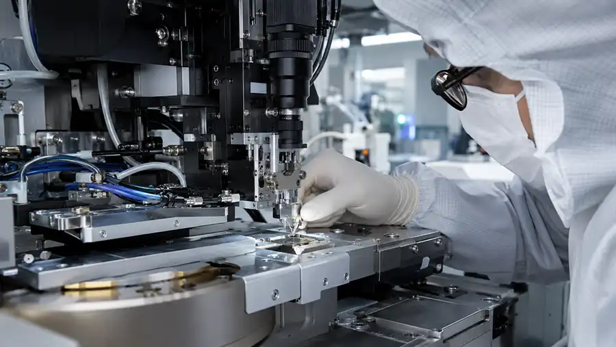
When to Explore a Different BESI Flip Chip Platform Direction
A specific BESI flip chip bonder should be shortlisted only when its installed configuration matches the required process route. A different platform direction may be more appropriate when the project requires higher-volume mass reflow production, a different multi-chip process sequence, more specialized fan-out handling, advanced interconnect requirements or a different level of process flexibility.
The goal is not to force every application into one DATACON or Esec platform family. The goal is to identify the configuration that has the clearest path to tooling availability, process validation, installation and repeatable production.
Final Recommendation: Compare the Process Chain Before Comparing the Machine Price
A BESI flip chip bonder can be a strong platform option when the offered machine has the correct die source configuration, flip tools, material preparation modules, handling path, vision package, fixtures, software environment and support scope.
Before approving a quotation, compare the complete process chain from die pickup through placement and inspection. This approach helps prevent a common mistake in used semiconductor equipment buying: purchasing a suitable platform family with an unsuitable installed configuration.
Related BESI Flip Chip Resources
Frequently Asked Questions About BESI Flip Chip Bonders
What is a BESI flip chip bonder?
A BESI flip chip bonder is semiconductor assembly equipment used to pick, flip, align and place die in flip chip packaging workflows. The exact process capability depends on the platform family and installed configuration, including handling modules, tooling, vision and process hardware.
What is the difference between a flip chip bonder and a flip chip mounter?
The terms are often used interchangeably. In practical equipment evaluation, the important issue is the actual production function of the machine, including die pickup, flip operation, material preparation, alignment, placement, inspection and handling sequence.
Which BESI flip chip bonder is suitable for mass reflow production?
Mass reflow flip chip projects should be evaluated against platforms and configurations designed for the required production speed, material flow, die handling, substrate route, vision system and process-control requirement. The exact machine configuration must be confirmed before selection.
Can a DATACON 2200 evo be used for flip chip applications?
Some DATACON 2200 evo configurations can be evaluated for selected flip chip workflows. Buyers should confirm flip tools, handling modules, vision alignment, material preparation, fixtures and application-specific process capability.
What should be checked before buying a used flip chip bonder?
Verify the exact machine version, bond heads, flip tools, nozzles, wafer and substrate handling modules, vision system, process modules, controller, software backups, tooling inventory, refurbishment scope and FAT proposal.
Why is tooling important for flip chip bonding?
Tooling can determine whether the machine can handle the target die, substrate and package route. Missing nozzles, flip tools, eject tools, carrier plates, fixtures or calibration references can delay qualification and increase project cost.
What should a flip chip bonder FAT include?
A useful FAT can include machine identity verification, safety checks, motion and bond head operation, vision alignment, handling-module tests, tooling confirmation, software backup review and a representative process sequence when suitable materials are available.
How do I compare two BESI flip chip bonder quotations?
Compare the full installed configuration rather than the platform name or purchase price. Review process route, bond heads, flip tools, material modules, handling hardware, vision package, tooling inventory, controller, software, refurbishment scope and FAT evidence.
Need Help Reviewing a BESI Flip Chip Bonder Configuration?
Share the available machine photos, serial information, package drawing, die size, substrate format, material route, target output, tooling details and expected process flow. A useful review begins with the actual package route and the physical configuration of the offered machine.