Moving a package onto an ASM AERO wire bonder is not only a machine setup task. Stable wire bonding depends on the combined behavior of wire material, capillary geometry, free-air ball formation, first-bond settings, second-bond settings, loop profile, workholder temperature, die pad condition, leadframe or substrate surface, vision alignment and machine setup.
For copper wire or other production wire materials, a process transfer should not be approved only because the machine can generate a ball and complete a dry cycle. The target package must be validated through a controlled bonding sequence that checks first-bond formation, second-bond consistency, loop geometry, placement stability and the process response of the actual materials.
This guide explains the main process variables that should be reviewed when transferring a package to an ASM AERO wire bonder, including capillary choice, wire feed, FAB behavior, looping, thermal conditions, vision setup and validation planning.
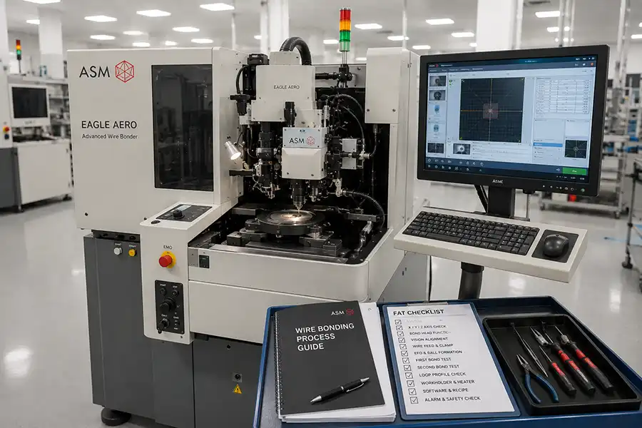
In Brief: What Controls Wire Bonding Stability on an ASM AERO Machine?
Wire bonding stability is controlled by the full process chain rather than by one machine setting. The most important variables typically include die pad condition, substrate or leadframe surface, wire material and diameter, capillary geometry, EFO behavior, first-bond parameters, second-bond parameters, loop profile, workholder temperature, vision alignment and process verification.
Do not change wire material without reviewing capillary, FAB and bond settings.
Do not use a capillary only because it worked on a previous package.
Do not approve a loop profile from a single location on one sample unit.
Do not assume a stable first bond guarantees stable second-bond performance.
Do not release a process until the actual package, materials and production conditions are validated.
Why AERO Process Transfer Is More Than Machine Setup
Machine setup is only one part of process transfer. A package may require new capillaries, different workholders, updated vision teach points, revised loop programming, new wire-feed settings or a changed thermal condition even when the same AERO wire bonder is already running another product.
The transfer becomes more sensitive when die pad metallization, leadframe plating, substrate finish, wire material, die thickness, pad geometry, package clearance or mold-related constraints change. The bonding machine must be configured around the actual physical process rather than a generic previous recipe.
Process-transfer principle: Validate the package, material and tooling combination as one system. Do not validate the wire bonder in isolation.
10 Variables That Control Wire Bonding Stability
1. Die Pad Metallization and Surface Condition
The first bond depends heavily on the condition of the die pad. Metallization type, pad cleanliness, oxidation, contamination, pad size, passivation opening, topography and die handling history can all influence bonding behavior.
Before changing machine settings, inspect whether the first-bond issue is related to the die pad itself. A process that was stable on one die source may behave differently when a new wafer lot, pad finish or die supplier is introduced.
2. Leadframe, Substrate or Package Bonding Surface
The second bond is influenced by the condition of the receiving bonding surface. Leadframe plating, substrate metal finish, bond finger geometry, contamination, flatness, package support and thermal behavior can affect stitch formation and bond consistency.
When second-bond variation appears, the problem may not be caused only by ultrasonic energy or force. Review the package material, plating condition, fixturing and workholder stability as part of the investigation.
3. Wire Material, Diameter and Lot Consistency
Wire material and wire diameter affect FAB formation, capillary interaction, bond deformation, loop behavior and process window. A change in wire type, diameter, coating, storage condition or supplier lot should be treated as a controlled process change.
Wire should be verified before running a production transfer. Confirm correct loading, routing, spool orientation, feed path cleanliness and compatibility with the installed capillary and bonding recipe.
4. Capillary Geometry and Tool Wear
Capillary geometry is one of the highest-impact variables in ball bonding. It affects free-air ball behavior, first-bond deformation, bond footprint, stitch formation, loop shape and clearance conditions.
Capillaries should be selected against wire diameter, pad geometry, bonded-ball target, leadframe or substrate design, loop requirement and package construction. A capillary that worked on one device may not be appropriate for another package.
Tool wear, contamination, damage or inconsistent geometry can cause unstable bonding even when machine parameters appear unchanged.
5. Wire Feed, Clamp and Tail Formation
Stable wire feed is necessary for repeatable FAB formation and loop generation. The wire path, clamp condition, clamp timing, tail length, capillary interface and feed response should be reviewed before making large changes to bond parameters.
Symptoms such as inconsistent free-air balls, unexpected wire breaks, unstable loop height or irregular first-bond behavior may be linked to wire feed, clamp movement or tail-control condition.
6. EFO and Free-Air Ball Formation
Free-air ball formation is a foundational part of ball bonding. The EFO system, electrode condition, wire tail, wire feed, capillary setup and gas environment can all influence the size, shape and consistency of the ball.
During process transfer, establish a stable FAB before attempting final first-bond optimization. A first-bond process cannot be reliably tuned when the incoming free-air ball is inconsistent.
7. First-Bond Parameter Balance
First-bond performance is affected by force, ultrasonic energy, bonding time, temperature, capillary condition, FAB condition, die pad quality and alignment accuracy. These variables should be adjusted through a controlled method rather than through broad simultaneous changes.
When first-bond results are inconsistent, use a structured review: confirm die pad condition, inspect capillary wear, verify FAB behavior, confirm alignment, then evaluate force, energy, time and thermal conditions.
8. Second-Bond and Stitch Formation
Second-bond quality depends on the receiving surface, stitch parameters, capillary geometry, wire tension, loop trajectory, workholder condition and thermal stability. A stable first bond does not guarantee a stable second bond.
Review stitch appearance and bond consistency across different package positions. Variation at one side of a leadframe or substrate may indicate fixture support, flatness, temperature or local alignment issues rather than a global recipe problem.
9. Loop Profile, Span and Loop Height
Looping should be designed around the package architecture. Loop height, span, heel geometry, wire clearance, die-to-lead distance, neighboring wires, mold flow and package constraints must all be considered.
A loop profile should be reviewed across the entire package, not only at one central bonding location. Edge positions, long spans, adjacent wires and difficult package corners can reveal issues that are not visible in a simple setup test.
10. Workholder Temperature and Thermal Stability
Temperature affects material behavior, substrate stability, leadframe response, bond formation and long-run consistency. The workholder, heater plate, fixture contact and package support should be checked before attributing variation only to bonding parameters.
For thermal-sensitive packages or longer production runs, evaluate whether temperature remains stable across the workholder and whether package support changes from one location to another.
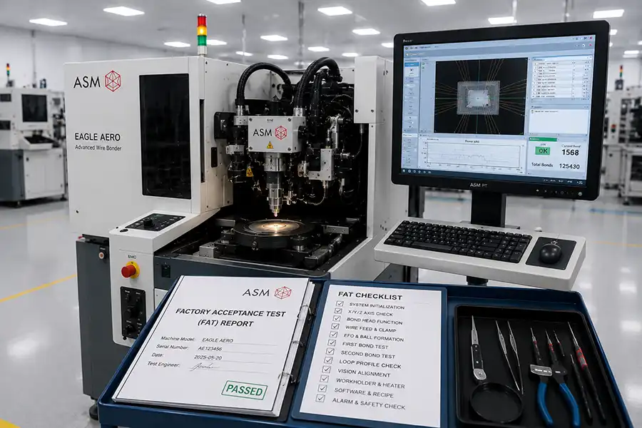
How to Run a Practical ASM AERO Process Transfer FAT
A process-transfer FAT should confirm that the offered machine can run the actual package route with representative material, appropriate tools and documented results. It should not be limited to machine initialization or a generic wire-bonding demonstration.
Step 1 — Confirm Package and Material Inputs
Prepare package drawings, die pad information, leadframe or substrate details, wire material, wire diameter, capillary proposal, workholder requirements and expected loop profile before starting the test.
Step 2 — Install Verified Capillary and Tooling
Use a capillary and workholder configuration appropriate for the target device. Record the capillary type, tool condition, wire type, fixture identity and machine setup before testing.
Step 3 — Establish Stable Free-Air Ball Formation
Verify repeatable FAB formation before finalizing first-bond settings. Observe ball consistency, wire-tail stability and the interaction between EFO, clamp control and capillary setup.
Step 4 — Validate First Bond on Representative Die Pads
Run controlled first-bond trials on actual or representative die pads. Review bond appearance, deformation, location, repeatability and process response before moving to full loop evaluation.
Step 5 — Validate Second Bond on Actual Package Surfaces
Confirm stitch formation, second-bond consistency and location accuracy on the actual leadframe, substrate or receiving metal surface. Include difficult bond locations where possible.
Step 6 — Confirm Loop Profile Across Package Locations
Evaluate loop height, span, shape, clearance and repeatability across central, edge and long-span positions. Record the loop program and any process limits identified during testing.
Step 7 — Review Vision Alignment and Teach Stability
Confirm that die pads, leads, substrates or package references can be recognized consistently. Verify teach points, camera settings, lighting and alignment performance using the target package.
Step 8 — Record Parameters, Results and Requalification Limits
Document wire material, capillary details, EFO conditions, bond parameters, heater settings, loop program, vision settings, inspection results and the conditions that require requalification.
Common Wire Bonding Symptoms and the First Variables to Review
| Observed Symptom | First Variables to Review |
|---|---|
| Small or inconsistent free-air ball | EFO condition, electrode status, wire feed, clamp movement, tail length, wire material and capillary setup. |
| First-bond inconsistency | Die pad surface, capillary geometry, FAB condition, alignment, force, ultrasonic energy, bond time and temperature. |
| Second-bond variation | Leadframe or substrate surface, stitch parameters, capillary wear, wire tension, workholder support and thermal condition. |
| Loop-height drift | Loop recipe, wire feed, clamp timing, tail length, capillary condition, machine calibration and package fixture stability. |
| Wire sweep or unstable loop profile | Loop design, wire span, package geometry, clearance conditions, material flow, mold-related constraints and process sequence. |
| Frequent wire breaks | Wire path, clamp condition, capillary damage, EFO behavior, wire feed, tool contamination and parameter balance. |
| Alignment variation between package positions | Vision teach points, camera focus, illumination, fixture flatness, package placement, stage condition and local reference features. |
When a Wire Bonding Process Must Be Requalified
A wire bonding recipe should be reviewed and potentially requalified when any process-critical input changes. This includes a change in wire material, wire diameter, capillary type, die pad finish, leadframe or substrate plating, package geometry, workholder, heater condition, machine controller, bonding head, vision configuration or major software environment.
Requalification does not always require rebuilding the entire process from zero. However, the changed variable should be identified, risk-assessed and validated against the actual package route before release to production.
What Should Be Documented During an AERO Process Transfer?
Exact machine model, serial number and installed configuration
Package drawing, die pad layout and receiving bonding surface
Wire material, diameter, supplier lot and storage condition
Capillary type, geometry, condition and replacement criteria
EFO setup, FAB condition and wire-tail settings
First-bond and second-bond parameter set
Loop profile, loop height, span and package clearance requirements
Workholder, heater and fixture identification
Vision teach points, camera settings and alignment method
Inspection observations, rejection criteria and requalification triggers
Final Recommendation: Validate the Complete Bonding System
An ASM AERO wire bonder can provide a strong process platform when the actual machine configuration, capillary tooling, wire material, workholder, package geometry, vision setup and validation method are aligned.
Before releasing a transferred product to production, confirm stable FAB formation, first-bond quality, second-bond consistency, loop profile, vision alignment and package-level repeatability. This prevents a common process-transfer mistake: validating a machine cycle without validating the actual package and material combination.
Related ASM Wire Bonder Resources
Frequently Asked Questions About ASM AERO Wire Bonder Process Transfer
What is the most important variable in copper wire bonding?
No single variable works independently. Wire material, capillary geometry, FAB condition, pad surface, bonding parameters, thermal conditions and loop design must be evaluated together as one process system.
How does capillary condition affect first-bond consistency?
Capillary geometry, wear, contamination and damage can affect FAB interaction, bond deformation, ultrasonic transfer, bond footprint and location accuracy. Capillary condition should be checked before making broad parameter changes.
Why is free-air ball formation important?
The FAB is the starting condition for the first bond. Inconsistent ball size, shape or wire-tail behavior can create unstable first-bond results even when other bonding parameters remain unchanged.
What affects loop height and loop stability?
Loop height and stability are influenced by loop program, wire feed, clamp timing, capillary condition, wire material, die-to-lead distance, package geometry, workholder support and machine calibration.
When should a wire bonding recipe be requalified?
A recipe should be reviewed when wire material, capillary type, die pad condition, leadframe or substrate finish, package geometry, workholder, bonding head, vision setup, heater condition or other process-critical inputs change.
Can one capillary be used for different package designs?
Sometimes, but suitability depends on wire diameter, pad geometry, bonded-ball requirement, lead or substrate design, loop target and package clearance. Capillary compatibility should be confirmed for each process route.
Why does second-bond quality vary between substrate lots?
Variation can be influenced by surface finish, plating condition, contamination, flatness, fixture support, thermal behavior, stitch parameters and local alignment conditions. The receiving surface should be reviewed alongside bonding settings.
What should be documented during an ASM AERO process transfer?
Document the machine configuration, wire and capillary details, EFO condition, bond parameters, loop program, workholder setup, vision settings, package materials, inspection findings and requalification limits.
Need Help Reviewing an ASM AERO Wire Bonding Process?
Share the package drawing, die pad layout, leadframe or substrate details, wire material, wire diameter, capillary information, target loop profile, workholder conditions and expected production requirements. A useful review starts with the complete package process rather than one bonding parameter alone.