Siemens SIPLACE D3i SMT Machine Comprehensive Technical Analysis
1. Equipment Positioning and Market Background
1.1 Equipment Positioning
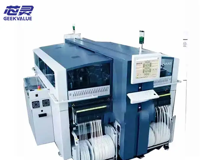
Product Line Position: D3i is a mid-to-high-end modular SMT machine of Siemens (now ASM SIPLACE), positioned in the SMT production line with high speed, high precision and high flexibility, suitable for large-volume and multi-variety electronic manufacturing (such as automotive electronics, communication equipment, and high-end consumer electronics).
Iteration Relationship: D3i is an upgraded model of the D series. Compared with the D1/D2 series, it optimizes the dynamic accuracy and line change efficiency, and supports more complex component placement (such as special-shaped components and large-size BGA).
1.2 Technology Inheritance
Brand Ownership: Siemens SMT business later belonged to ASM Assembly Systems, but continued the SIPLACE technology system.
Core Advantages: Inheriting SIPLACE linear motor drive, Fly Vision and other patented technologies.
2. Core working principle
2.1 Mounting process
PCB transmission and positioning
PCB enters the machine through high-precision guide rails and is fixed by mechanical clamping + vacuum adsorption.
FCM camera identifies PCB fiducial points (Fiducial) to compensate for PCB deformation or position deviation.
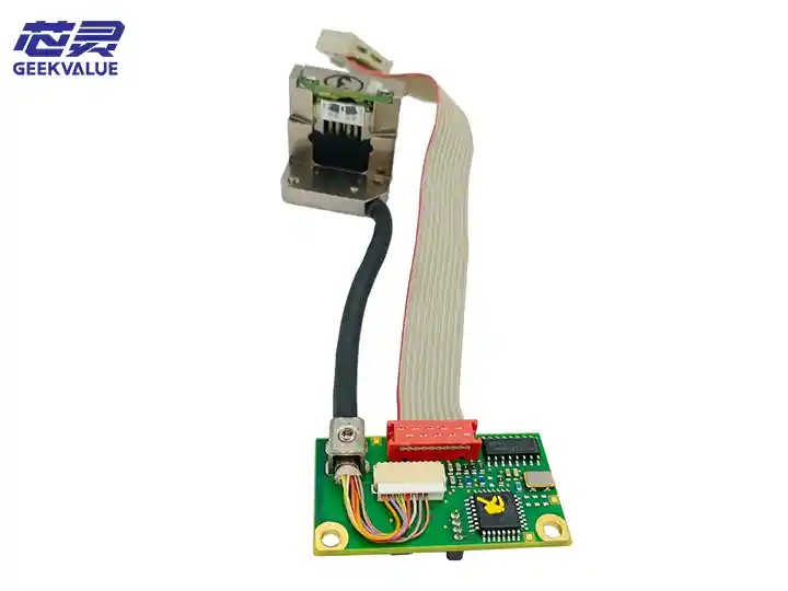
Component picking and calibration
The mounting head picks up components from the feeder and detects components in real time through the ICM camera (integrated camera module):
Center position offset
Rotation angle error
Pin coplanarity (for QFP/BGA)
Using flying centering technology, components are calibrated during movement to reduce pause time.
Dynamic mounting
Linear motor drives the mounting head, combined with grating ruler closed-loop control, to achieve nanometer-level positioning (±15μm @3σ).
Supports force control mounting to prevent damage to precision components (such as thin MLCC).
2.2 Core Technology
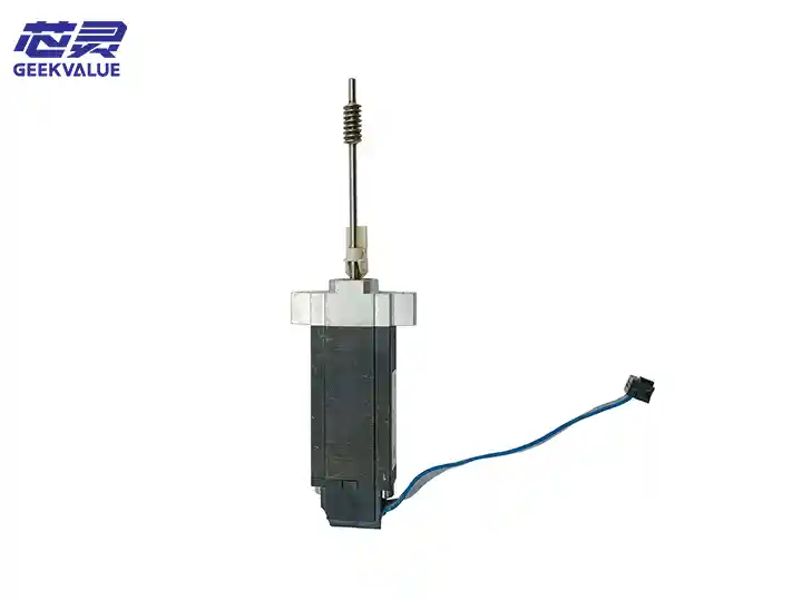
Linear Direct Drive Technology: Frictionless transmission, speed up to 2m/s², lifespan far exceeds traditional lead screw.
MultiStar placement head: Optional 12/16 nozzle head, supports Pick & Place Parallelism.
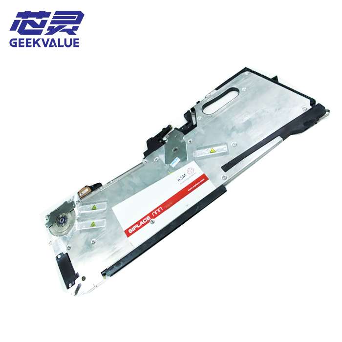
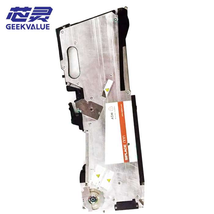
Intelligent feeding system:
Supports electric feeder (eFeeder), automatically calibrates position when changing materials.
Can be expanded to 300+ material stations, compatible with 8mm~104mm material tapes.
3. Hardware and software configuration
3.1 Hardware architecture
Module Functional description
Placement head MultiStar series, optional 12/16 nozzle, supports 0201~45mm×45mm components.
Vision system - ICM (component calibration): 50μm@15ms
- FCM (PCB positioning): ±10μm accuracy
Feeding system Electric feeder (eFeeder), supports intelligent bin management.
Motion control Linear motor + grating ruler, repeatability ±15μm.
Conveyor system Dual-track conveyor, supports PCB size 50mm×50mm~510mm×460mm.
3.2 Software system
SIPLACE Software Suite:
Pro: Basic programming and optimization.
Xpert: Advanced data analysis (such as CPK, placement offset statistics).
Monitor: Real-time production monitoring (OEE, fault alarm).
Intelligent optimization function:
Dynamic placement sequence optimization: Reduce the moving distance of the head arm.
Line change assistance (QuickChange): Automatically identify changes in material station position.
4. Key performance parameters
Indicators D3i parameters
Maximum placement speed 60,000 CPH (theoretical value, actual depends on component mixing)
Placement accuracy ±15μm @3σ (chip components), ±35μm (large BGA)
Component range 0201~45mm×45mm, thickness 0.2~12mm
Feeder capacity Maximum 324 (8mm tape)
Line change time <5 minutes (QuickChange mode)
5. Industry application scenarios
Automotive electronics: ECU control board (high temperature resistant component placement).
Communication equipment: 5G base station RF module (high density BGA).
Medical electronics: Implantable device PCB (ultra-fine pitch components).
Industrial control: High reliability industrial control motherboard.
6. In-depth troubleshooting and maintenance
6.1 Common faults and solutions
Fault 1: Component placement offset
Possible causes:
PCB positioning is inaccurate (fiducial recognition error).
Nozzle wear causes pickup height deviation.
Solution:
Clean the FCM camera and recalibrate the reference point.
Use the nozzle height calibrator to adjust the Z-axis parameters.
Fault 2: Vacuum pickup failure
Possible causes:
Nozzle blockage or vacuum pipeline leakage.
Component thickness parameter setting error.
Solution:
Clean the nozzle with an ultrasonic cleaner.
Check the vacuum generator pressure (standard value: -80~-90kPa).
Fault 3: Drive alarm (ERR-2105)
Possible causes: Linear motor overload or encoder failure.
Solution:
Manually check whether there is foreign matter on the guide rail after power off.
Contact ASM technical support to replace the drive module.
6.2 Preventive maintenance plan
Cycle Maintenance content
Daily - Clean the nozzle, camera lens
- Check the vacuum pressure
Weekly - Lubricate the linear guide
- Calibrate the Z-axis height of the placement head
Monthly - Fully calibrate the visual system
- Backup equipment parameters
7. Comparative analysis of competitive products
Model SIPLACE D3i FUJI NXT III Panasonic CM602
Speed (CPH) 60,000 75,000 50,000
Accuracy (μm) ±15 ±25 ±30
Line change time <5 minutes 10 minutes 8 minutes
Advantages High dynamic accuracy Ultra-high speed Large board compatibility
8. Summary
SIPLACE D3i, with its linear direct drive technology, intelligent feeding system and modular design, excels in high-precision complex placement scenarios, and is particularly suitable for high-end manufacturing fields such as automotive electronics and communication equipment.
Recommendations:
Regular maintenance can extend the life of the equipment (focus on linear guides and vacuum systems).
We recommend that you quickly resolve complex faults through our remote diagnostic service.
For more detailed mechanical manuals or software operation guides, visit the ASM official technical support portal.