EN
EN id
id sk
sk sr
sr sv
sv it
it pt
pt bn
bn ms
ms be
be nl
nl fr
fr th
th vi
vi ru
ru ja
ja ko
ko de
de hy
hy az
az bs
bs bg
bg my
my cs
cs da
da dv
dv el
el et
et fil
fil fi
fi ga
ga gl
gl gn
gn he
he hi
hi km
km hr
hr hu
hu is
is kn
kn rw
rw lo
lo lv
lv lt
lt lb
lb lg
lg mi
mi mt
mt ne
ne no
no ny
ny or
or om
om per
per pl
pl ro
ro sa
sa so
so es
es sw
sw ta
ta tr
tr uk
uk ur
ur cy
cy xh
xh
A used wire bonder should be evaluated as a complete bonding system, not only by its brand, model or exterior condition. The machine, bond head, wire path, bonding tool, workholder, vision system, software and package materials must operate together as one process.
A power-on demonstration can show that the machine starts and that its main axes move. It does not prove that the offered system can feed the intended wire, create stable bonds, maintain the required loop profile or produce acceptable bond-test results.
The most useful inspection therefore begins with the intended package process, continues with the exact machine configuration and ends with documented bonding evidence. Buyers who first need an overview of bonding methods and equipment types can review the wire bonder technology guide.
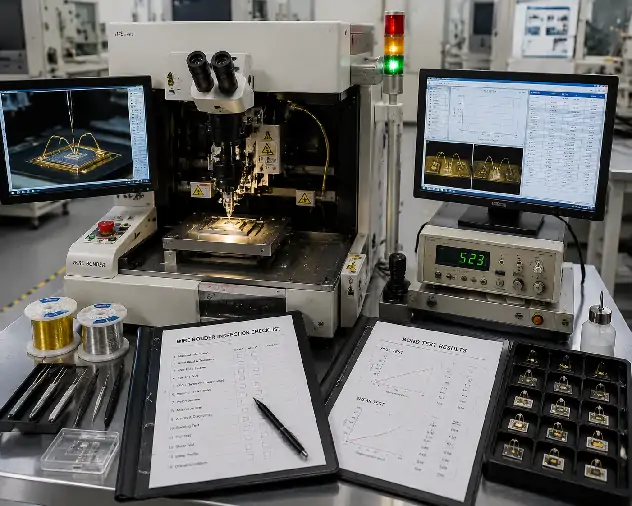
Define the Bonding Process Before Inspecting the Machine
A wire bonder cannot be accepted against a general statement such as “the machine runs normally.” The buyer should first define the package, wire, bonding method and production result that the machine is expected to support.
| Process Input | Information to Prepare | Why It Affects Machine Acceptance |
|---|---|---|
| Bonding method | Ball bonding, fine-wire wedge bonding, heavy-wire bonding or ribbon bonding | Each process requires a different bond head, tool interface, wire path and bonding sequence. |
| Wire or ribbon | Material, diameter or ribbon dimensions, supplier and intended spool format | The feed system, clamp, tool, ultrasonic setup and process window must match the selected material. |
| Package | Die size, pad layout, leadframe or substrate, package dimensions and bond locations | The package determines the bonding area, workholder, vision references and required machine travel. |
| Bond surfaces | Die-pad material, leadframe plating, substrate finish and surface condition | Bond parameters and achievable results depend on the complete material interface. |
| Loop requirement | Loop height, span, direction, clearance and any low-loop or long-loop requirement | Loop capability must be demonstrated on representative package geometry. |
| Thermal condition | Required workholder temperature, package heating and allowable thermal exposure | The heater and fixture must maintain the required process condition without damaging the product. |
| Quality criteria | Visual limits, loop measurements, pull or shear method and applicable acceptance requirements | The FAT needs measurable criteria rather than a subjective judgment that the bonds look acceptable. |
| Production target | Package format, wires per device, output target, changeovers and automation needs | A stable sample run does not automatically confirm the required production rate or handling flow. |
These inputs do not need to become a complete production recipe before the inspection begins. They should, however, be detailed enough to identify which machine functions, tooling and test results matter to the project.
Connect Every Inspection Record to the Exact Machine
The machine serial number should connect the quotation, photographs, configuration record, inspection report, FAT results and final packing list. Images from another machine of the same model do not confirm what is installed on the offered unit.
| Configuration Area | What to Record | What the Record Helps Confirm |
|---|---|---|
| Machine identity | Full model, variant, serial number, manufacturing record and nameplate | That every document refers to the same physical machine |
| Bond head and transducer | Head type, transducer identification, tool interface, service history and visible condition | Whether the installed bonding system matches the intended process |
| Wire-feed system | Spool arrangement, guides, tension components, feed path, clamps and cutter | Whether the machine can feed and control the intended wire or ribbon |
| EFO system | EFO wand, discharge condition, positioning and related hardware on ball bonders | Whether free-air-ball formation can be demonstrated where the process requires it |
| Bonding tools | Capillaries, wedges, tool holders, clamps and included replacement items | Whether suitable tools are available for the wire and package |
| Workholder and heater | Fixture, clamps, support surfaces, heater plate, temperature control and sensors | Whether the package can be held and heated consistently |
| Vision system | Cameras, optics, lighting, pattern-recognition functions and calibration status | Whether package references and bonding locations can be recognized reliably |
| Material handling | Manual loading, magazine handler, leadframe transport, indexing and unloading modules | Whether the machine can support the intended production flow |
| Controller and software | Controller generation, software version, active options, recipes, backups and recovery information | Whether the machine can be restored, programmed and supported after delivery |
| Utilities and safety | Power, compressed air, exhaust, guards, interlocks and emergency-stop functions | Whether the system can be installed and operated safely at the receiving factory |
Not every wire bonder uses the same hardware. An EFO system and free-air-ball sequence are relevant to ball bonding, while wedge and heavy-wire systems use different wire-control, tool and cutting arrangements. The inspection checklist must follow the actual bonding technology rather than applying ball-bonder terminology to every machine.
Separate Basic Machine Motion from Process Evidence
Inspection evidence becomes more valuable as it moves from general machine activity toward a representative bonding process.
| Evidence Level | What Can Be Demonstrated | What Remains Unproven |
|---|---|---|
| Power-on inspection | Startup, controller access, safety status and visible alarms | Bonding capability, material compatibility and process stability |
| Dry-cycle demonstration | Axis motion, indexing, vision movement and basic automation sequence | Wire feed, tool interaction, bond formation and bond strength |
| Functional bonding test | Wire feed, clamp action, tool movement, first and second bonds and basic looping | Compatibility with the buyer’s package and production acceptance criteria |
| Application-based FAT | Representative package loading, bonding sequence, loop formation, visual result and test data | Long-term production performance beyond the agreed test conditions |
| Production qualification | Performance against the buyer’s materials, criteria, output and reliability plan | Conditions outside the qualified process window |
A useful FAT does not need to claim that the machine is already qualified for every future product. It should clearly state which functions and materials were tested, which results were measured and which production risks still require validation after installation.
Build the FAT Around the Complete Bonding Sequence
The Factory Acceptance Test should follow the process from material loading to the final bond and recorded result. The exact sequence will differ between ball, wedge, heavy-wire and ribbon bonding systems.
| FAT Stage | Test Activity | Evidence to Retain |
|---|---|---|
| Startup and status | Start the machine, home the axes and review active alarms and module status. | Startup video, software version, configuration screen and alarm record |
| Tool installation | Install the applicable capillary, wedge or ribbon tool and confirm the tool interface. | Tool identification, holder condition and setup record |
| Wire loading | Route the selected wire or ribbon through the installed feed and clamp system. | Wire material, dimensions, spool information and routing photographs |
| Wire-control functions | Operate the feeder, tension control, clamp, cutter and tail-control sequence where applicable. | Functional video, alarms and observed feed stability |
| Ball formation | Demonstrate free-air-ball formation when testing a ball-bonding process. | Ball images, stability observations and relevant setup conditions |
| Vision alignment | Teach and recognize die, substrate or leadframe references. | Camera images, recognition results and alignment-repeatability observations |
| First bond | Create the first bond using representative material and the agreed process direction. | Bond images, process parameters and inspection observations |
| Loop formation | Run representative short, long, central and edge-position loops where relevant. | Loop profile, height, clearance and consistency measurements |
| Second bond | Complete the stitch or wedge bond and confirm wire termination. | Bond images, tail result, wire-break location and inspection observations |
| Repeated operation | Run enough continuous cycles to reveal intermittent feed, recognition, bonding or handling problems. | Cycle record, alarms, missed bonds, wire breaks and operator interventions |
| Recipe and recovery | Save the process, restart the machine and confirm that the required settings and data can be recovered. | Recipe files, backup location and recovery demonstration |
The required number of devices, wires or repeated cycles should be agreed before testing. It should reflect the purpose of the FAT rather than being selected only because a short demonstration is convenient.
Use Bond Tests to Measure the Result
Machine motion and visual appearance do not directly measure bond strength. Where the project requires quantitative evidence, the test plan can include wire pull, ball shear or another applicable mechanical test.
Visual and Dimensional Inspection
Visual inspection can assess bond position, deformation, tail condition, visible damage, wire sweep and loop clearance. Dimensional inspection can record loop height, bond geometry or other package-specific measurements.
These checks are important, but a visually acceptable bond should not automatically be treated as proof of mechanical strength.
Wire Pull Testing
A wire pull test applies a controlled load to the bonded wire or ribbon. The report should record the test setup, tool position, measured result and failure mode.
The failure location can be as important as the force value. A wire break, bond lift, heel failure, pad damage or substrate failure may indicate different process or material conditions.
Ball Shear and Other Shear Tests
Ball shear may be appropriate for evaluating a ball bond when the package design and selected test method support it. Shear testing should not be added mechanically to wedge or heavy-wire projects without confirming that it is the correct method for the bond structure being evaluated.
Integrated Process Monitoring
Some wire bonders offer process monitoring, inline pull testing or non-destructive quality functions. Their availability depends on the machine model, installed hardware and active software options.
Integrated monitoring can provide useful process evidence, but it should be reviewed together with the buyer’s validation method. A monitoring screen alone does not confirm that the correct limits, calibration and package process have been established.
Review Repeatability and Recovery Behavior
A single successful device is not enough to show that the machine can run consistently. Repeated operation should be used to observe:
Wire-feed consistency and clamp response
Free-air-ball stability on ball bonders
First-bond and second-bond consistency
Loop height and shape across the bonding area
Pattern-recognition and teach-point stability
Package indexing and workholder support
Wire breaks, missed bonds and false alarms
Recovery after a stopped cycle or material interruption
Condition after warm-up and continuous running
The FAT record should identify any manual adjustments or operator interventions required to complete the run. A result obtained only after repeated unrecorded corrections is not equivalent to a stable, repeatable sequence.
Confirm Software, Recipes and Machine Recovery
A mechanically complete wire bonder can still create significant commissioning delays when the controller, software or recipe environment is incomplete.
Before shipment, verify:
The installed software version and active machine options
Access to the required programming and setup functions
Available package recipes and their relevance to the intended process
Machine parameters, calibration files and configuration backups
Industrial computer, storage device and communication condition
Recovery media, passwords and available technical documentation
Interface requirements for handlers, factory systems and traceability
Existing recipes may provide a useful process reference, but they should not be assumed to work with a different wire, tool, pad finish, package, fixture or thermal condition.
For a more focused example of package-process validation, review the K&S IConn PLUS wire bonder FAT guide. ASM platform projects can also use the used ASM AERO wire bonder buying guide for model-family checks.
Match the Delivery List to the Tested Configuration
The final packing list should describe the same configuration used during inspection and FAT. A machine may complete a bonding test and still arrive without the tool holders, workholders, heater parts or software items required to reproduce the result.
Confirm whether the delivery includes:
The identified machine, controller and industrial computer
The tested bond head, transducer and tool interface
Capillary or wedge holders and the agreed bonding tools
Wire spool hardware, guides, clamps, cutters and feed accessories
EFO hardware for the applicable ball-bonding configuration
Workholders, heater plates, clamps and package fixtures
Cameras, optics, lighting and vision accessories
Handlers, magazines, tracks and material-transfer parts
Software, licenses, recipes, backups and available manuals
Calibration items, maintenance tools and agreed spare parts
Known-defect records and components removed for transport
Sensitive motion assemblies, bond heads, optics and handling modules should be secured under an agreed packing plan. Removed items should be labelled so that the receiving team can identify their installation position.
When a General Wire Bonder FAT Is Not Enough
A generic functional test may be insufficient when:
The product uses a new wire material, diameter or ribbon format.
The package requires unusually low, long or complex loops.
The die pad or substrate finish differs from the available test material.
The application requires fine-pitch, high-current or highly sensitive bonding.
The machine has undergone major bond-head, controller or software changes.
The required workholder, heater or automation hardware is not available during testing.
The project depends on customer-specific reliability or qualification standards.
In these cases, the machine may still be a viable candidate, but the remaining process-development and qualification work should be stated clearly before purchase.
Used Wire Bonder FAQ
Is a power-on video enough to approve a used wire bonder?
No. It can confirm startup and basic motion, but it does not prove wire feeding, bond formation, loop control, visual alignment, bond strength or compatibility with the intended package.
Should every wire bonder FAT include an EFO test?
No. EFO and free-air-ball formation apply to ball-bonding systems. Wedge, heavy-wire and ribbon bonders use different bonding and wire-termination arrangements.
What is the difference between wire pull and ball shear testing?
Wire pull applies a controlled load to the wire or ribbon, while ball shear applies a lateral load to an applicable ball bond. The correct method depends on the bond structure, package and selected acceptance procedure.
Can a general bonding sample prove production readiness?
It can demonstrate selected machine functions, but production readiness requires validation with the intended wire, bonding tool, package, fixture, thermal condition, acceptance limits and production sequence.
What information should be included in a used wire bonder quotation?
The quotation should identify the exact machine, installed configuration, known condition, included tools and fixtures, software status, test scope, measured evidence, unresolved items, packing responsibility and final delivery list.
Final Recommendation
A used wire bonder should be purchased as a verified bonding configuration rather than as a model name. Define the process first, connect every record to the exact machine, separate dry-cycle evidence from real bonding evidence and agree on measurable FAT criteria before shipment.
The available wire bonding equipment can then be compared against the required bonding method, package and production route. To review an identified machine, send its nameplate, configuration photographs, wire details, package information and proposed test scope through the All-SMT contact page.