EN
EN id
id sk
sk sr
sr sv
sv it
it pt
pt bn
bn ms
ms be
be nl
nl fr
fr th
th vi
vi ru
ru ja
ja ko
ko de
de hy
hy az
az bs
bs bg
bg my
my cs
cs da
da dv
dv el
el et
et fil
fil fi
fi ga
ga gl
gl gn
gn he
he hi
hi km
km hr
hr hu
hu is
is kn
kn rw
rw lo
lo lv
lv lt
lt lb
lb lg
lg mi
mi mt
mt ne
ne no
no ny
ny or
or om
om per
per pl
pl ro
ro sa
sa so
so es
es sw
sw ta
ta tr
tr uk
uk ur
ur cy
cy xh
xh
Comparing the ASMPT MS100 vs MS100 Plus vs MS100 Plus II is difficult because public listings use inconsistent equipment names and rarely provide a complete, independently verified specification set. The three models are commonly associated with wafer-map-based die handling, sorting or related pick-and-place processes, but the capability of any used machine depends on its installed hardware, software, tooling and condition.
A Plus or Plus II designation does not by itself establish higher throughput, greater accuracy, larger wafer support, additional heads or more advanced vision. Model names help narrow the search, but the nameplate, original documentation and demonstrated process should control the purchasing decision.
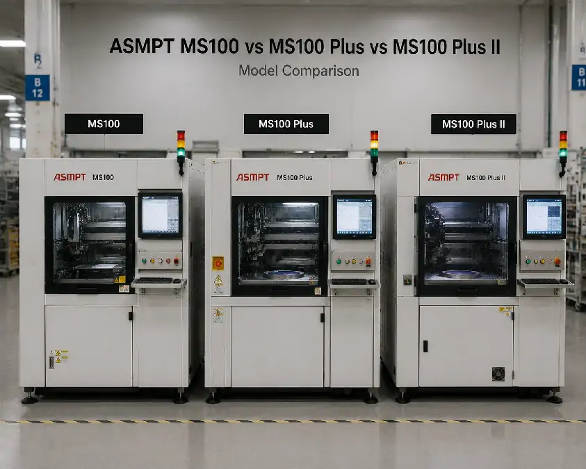
What Can Safely Be Said About the Three ASM Model Names?
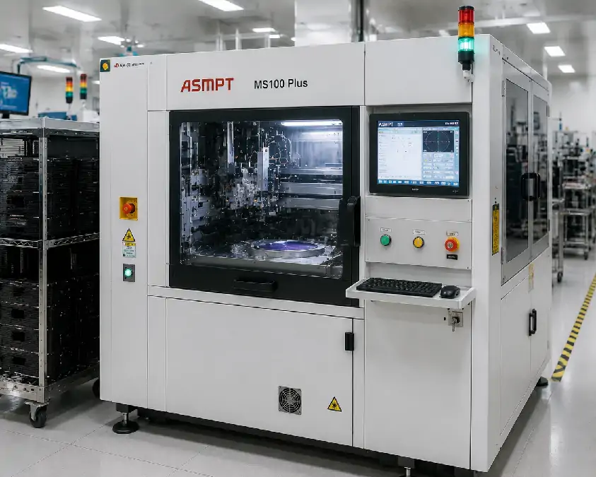
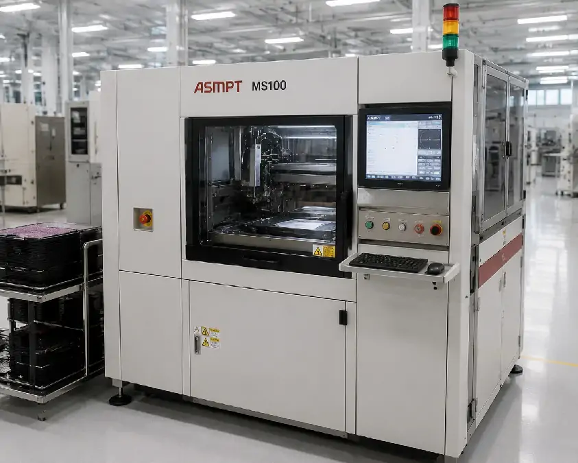
MS100, MS100 Plus and MS100 Plus II should be treated as separate model targets. Legacy machines may carry ASM branding, while current searches often use ASMPT, but the exact manufacturer and model designation should always be confirmed from the machine nameplate.
Marketplace listings may describe these systems as map sorters, die sorters, chip sorters or semiconductor pick-and-place machines. Those labels can help identify possible equipment, but they do not establish the installed process.
Wafer-map sorting generally uses map, recipe or classification information to select dies and route them to assigned outputs. Electrical test handling is different because it normally requires compatible test interfaces, contact hardware, ATE communication and supporting software. Die bonding is another separate process because it attaches dies to a substrate, package or other target.
Readers needing deeper unit-specific guidance can review the ASM MS100 model guide and the ASM MS100 Plus buying guide. This page compares all three models through one purchasing framework rather than repeating the individual guides.
A Controlled Comparison of MS100, MS100 Plus and MS100 Plus II
| Comparison Area | MS100 | MS100 Plus | MS100 Plus II |
|---|---|---|---|
| Model identity | Confirm the exact nameplate and machine record | Confirm the Plus designation and supporting documentation | Confirm the exact Plus II designation and machine record |
| Public market description | Often listed as map-sorting or pick-and-place equipment | Often presented as a related or later sorting platform | Marketplace terminology is especially inconsistent |
| Relationship between models | Do not infer later-model features | Relationship to MS100 requires documentary evidence | Relationship to earlier models requires documentary evidence |
| Wafer and frame handling | Check the installed machine | Check the installed machine | Check the installed machine |
| Pickup, ejector and tooling | Unit-specific | Unit-specific | Unit-specific |
| Vision capability | Confirm from installed hardware | Confirm from installed hardware | Confirm from installed hardware |
| Output configuration | Inspect the actual output route | Inspect the actual output route | Inspect the actual output route |
| Software and map handling | Demonstrate on the machine | Demonstrate on the machine | Demonstrate on the machine |
| Best purchasing evidence | Nameplate, documentation and process trial | Nameplate, documentation and process trial | Nameplate, documentation and process trial |
This table shows where evidence is required. It deliberately avoids unsupported comparisons of speed, accuracy, head count, wafer size, die range, camera count or output-bin capacity.
Define the Required Process Before Comparing the Machines
A useful comparison starts with the target process rather than the model suffix.
Define the die dimensions and thickness, device material, surface sensitivity, permitted pickup area and required orientation. The input requirements should identify the wafer or film-frame format, frame dimensions, wafer condition, loading method and source of map or recipe information.
The output route should also be clear. Specify whether dies must move to a tray, carrier, frame, bin or grade destination, including good, reject and rework routing where applicable. Vision, alignment, traceability, production use, changeover frequency and required inspection evidence should be included in the process definition.
A machine should only move onto the shortlist when its actual configuration can be compared with these requirements.
Wafer Handling, Pickup Hardware and Conversion Needs
The physical input and transfer configuration may matter more than the apparent model generation. For each available unit, compare the wafer or film-frame format, frame dimensions, wafer-table hardware, loading arrangement, support condition, ejector configuration and identification requirements.
Pickup compatibility depends on the installed head or arm, collet, nozzle or other pickup tool, vacuum condition, ejector mechanism and permitted die-contact area. Orientation control and available conversion tooling should also be reviewed.
For each machine, establish what is already installed, what tooling is included, what must be converted and whether the required parts remain available. The supplier should also explain whether the converted process can be demonstrated before shipment.
A newer-sounding model may require more conversion work than an older unit already configured for the target die and wafer frame. The lower-risk option is the machine with the closer installed match, not necessarily the later suffix.
Vision, Software and Wafer-Map Handling
Vision capability should be evaluated through the installed cameras, optics, lighting, viewing arrangement and actual recognition results. The machine record should show whether relevant recipes are available, whether calibration can be confirmed and whether the target die can be recognized in the required orientation.
The Plus or Plus II name does not establish a more advanced vision system. A camera may be present without providing the inspection or alignment function required for the buyer’s process.
Software comparison should cover successful boot, user access, passwords, license status, program backups, recipe availability, map loading, data-transfer method, alarm history, calibration records and manuals.
These functions should be demonstrated separately on each machine. Recipes, map formats, licenses and software backups should not be assumed to transfer between MS100, MS100 Plus and MS100 Plus II.
Output Routes, Tooling and Delivery Scope
The output configuration determines where selected dies can be placed and how grades or process results are separated. Compare the installed carrier, tray, frame or bin format, available destinations, orientation control and good, reject or rework routes.
A machine may have suitable input and pickup hardware but still be impractical if its output route does not match the required carrier or grade arrangement. Output changeover parts and traceability requirements should therefore be reviewed before the unit is shortlisted.
The commercial comparison also needs a clear delivery scope. Confirm whether each offer includes pickup tools, ejector parts, wafer frames, output carriers, conversion kits, computers, monitors, manuals, software backups and spare parts.
Inspection, calibration, conversion, refurbishment, export preparation, installation and training should be listed separately where applicable. Machine prices are not directly comparable until the included tooling, required work and delivery scope are understood.
Use the Same Condition and FAT Standard for All Three Machines
A fair comparison requires equivalent evidence. Request the nameplate, exact model, serial number, available manufacturing information, previous application and current operating status for every machine under consideration.
Review mechanical condition across the wafer table, pickup and ejector areas, motion systems, cameras, lighting, vacuum and pneumatic components, cables, guards, interlocks and computer hardware. Any repair or refurbishment claim should be supported by a documented scope.
Where practical, comparable operating evidence should cover:
Power-on and software boot
Axis homing and manual movement
Wafer-table and pickup-head movement
Camera image and recognition result
Map or recipe loading
Pickup and placement
Routing to the required output positions
Alarm recovery and repeated cycles
The strongest comparison uses the same target or representative die, wafer or frame, map or recipe, pickup requirement and output carrier on each machine. The achievable FAT scope will still depend on machine condition, tooling, software access, sample availability and seller capability.
A power-on video confirms only limited status. It does not establish process compatibility, complete tooling, reliable output routing or production readiness.
Which Machine Should a Buyer Choose?
An MS100 may be a strong candidate when the available unit already has the required input configuration, pickup tooling, software access, output route and demonstrated process capability. It should not automatically be treated as the basic or inferior option.
An MS100 Plus deserves further consideration when the specific unit provides a verified project advantage, such as better-matched tooling, a more suitable input or output arrangement, usable recipes, stronger operating evidence or lower conversion effort. That advantage belongs to the individual machine, not every unit carrying the Plus designation.
An MS100 Plus II should move ahead only when its exact machine record and process evidence show a closer fit. The Plus II name alone does not establish higher throughput, greater accuracy, more advanced vision, wider application coverage or better used-machine condition.
Choose the machine with the strongest verified process fit, not the most advanced-sounding model name.
Buyers who have not selected a model can review available semiconductor sorting machines and compare actual units according to the required die, media, tooling, software and output route.
Compare Available MS100, MS100 Plus and MS100 Plus II Machines
Before requesting a model-matching review, provide the die dimensions and thickness, material and surface condition, wafer or film-frame format, map and recipe requirements, pickup restrictions, vision needs, output carrier, sorting logic, existing tooling, required FAT evidence and delivery destination.
Contact All-SMT by WhatsApp or email to request actual machine photographs, nameplates, installed configurations, software and tooling records, available operating evidence and delivery scopes. Reference images or process documents can be attached after the WhatsApp or email conversation is opened.
Where valid product records exist, buyers can review available ASM MS100 equipment, ASM MS100 Plus machine details and the ASM MS100 Plus II configuration as equal model-level paths. These references do not imply that all three models are currently available.
The final quotation and recommendation should be based on the actual equipment and the target process rather than the model suffix alone.
Frequently Asked Questions About the ASM MS100 Series Comparison
What is the difference between the ASM MS100, MS100 Plus and MS100 Plus II?
The exact differences require original documentation and individual machine records. Public resale descriptions are not consistent enough to support a reliable universal comparison of speed, accuracy, wafer range or installed features.
Is the MS100 Plus always better than the MS100?
No. A specific MS100 Plus is only the better choice when its configuration, condition, tooling, software and demonstrated process capability fit the application more closely.
Is the MS100 Plus II automatically the most capable model?
No. Plus II is a separate model designation, but the name does not establish a universal performance or configuration advantage. Its actual hardware and process evidence must be reviewed.
Are these machines die sorters or electrical test handlers?
They are commonly associated with wafer-map-based die handling or sorting. Electrical testing should only be claimed when compatible test interfaces, ATE communication, process hardware and supporting documentation are present.
Can tooling be transferred between the three models?
Interchangeability should not be assumed. Pickup tools, ejectors, wafer tables, output fixtures, mechanical interfaces, software and calibration requirements must be checked for the exact machines.
Which model should be selected for a specific die?
Compare the die and wafer requirements with each unit’s installed pickup hardware, map handling, vision, output route, tooling and representative process evidence. Select the machine with the strongest verified match.
Conclusion: Public descriptions of the ASM MS100, MS100 Plus and MS100 Plus II are incomplete and inconsistent, so the three models should not be compared through unsupported specifications or suffix-based assumptions. Buyers should apply the same evidence standard to each unit and compare its identity, wafer handling, pickup hardware, vision, software, tooling, output configuration, condition and delivery scope. Equivalent FAT or representative process trials provide stronger guidance than marketplace labels, and the best choice is the machine with the strongest verified fit for the actual die-sorting process.