Existing AD830 Production
Evaluate a replacement or additional machine without assuming that every AD830 configuration is identical.
ave up to 70% on SMT Parts – In Stock & Ready to Ship
Get Quote →Understand how the ASM AD830 Plus die bonding machine fits a wafer-to-lead-frame silver-epoxy process. Review package compatibility, installed modules, tooling, production transfer and sample-acceptance requirements before introducing an AD830 platform into semiconductor assembly.
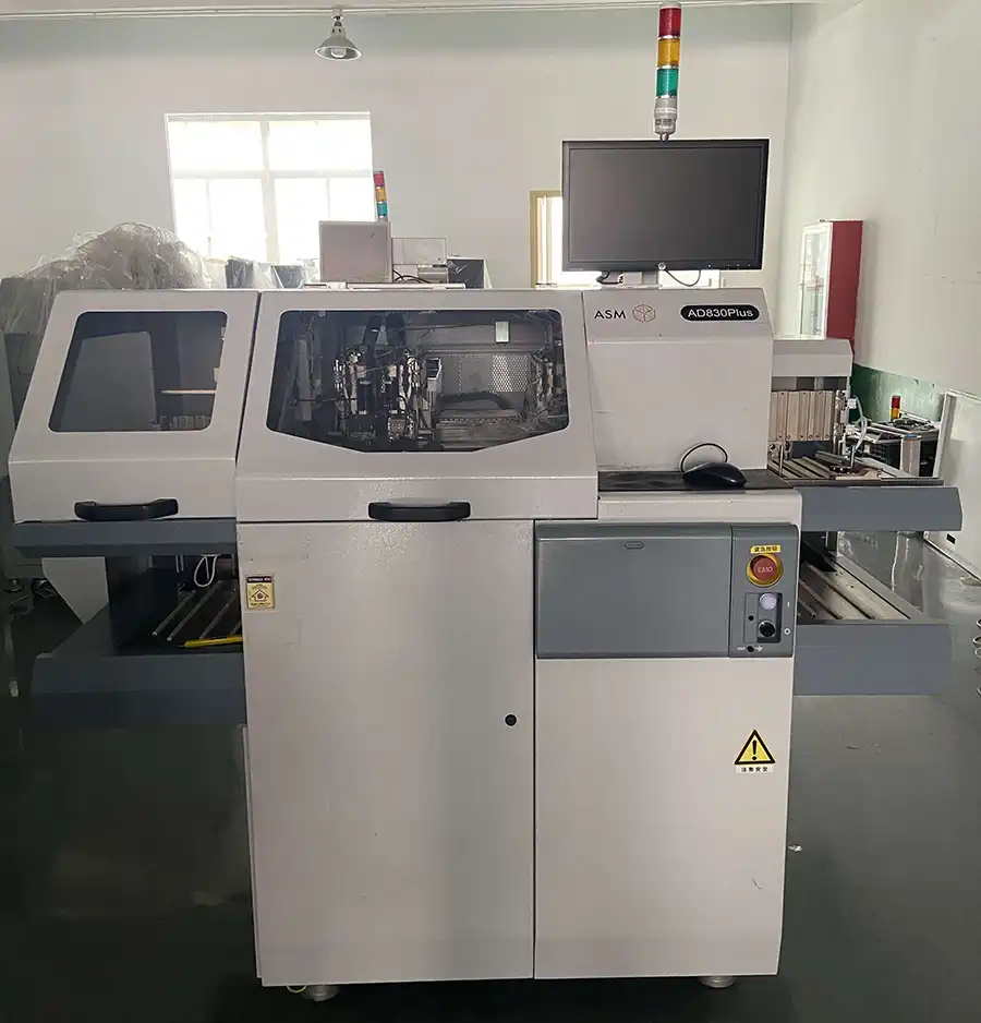
The ASM AD830 die bonder is an automatic semiconductor assembly platform developed for transferring individual dies from a wafer and placing them onto prepared lead-frame bonding positions. The model is commonly identified in machine records as the ASM AD830 Plus, AD830PLUS or ASM AD 830 PLUS.
Its production direction combines lead-frame handling, silver-epoxy application, wafer positioning, die recognition, ejector-assisted die separation, vacuum pickup, programmed placement and optical inspection. However, the model name does not show which input loader, wafer system, epoxy process, cameras, output elevator or tools are installed on a specific machine.
Evaluate a replacement or additional machine without assuming that every AD830 configuration is identical.
Determine whether the die, wafer, lead frame, epoxy method and inspection criteria fit the AD830 platform.
Build a clear package-transfer file covering tools, material settings, vision references and acceptance samples.
The AD830 Plus is most practical when the complete package flow is compatible with its wafer, lead-frame, epoxy, bond-head and inspection architecture. Use the following screening points before requesting a machine or preparing production transfer.
The platform may be a suitable direction when most of the following conditions apply:
A different platform or modified process may be needed in the following situations:
The production result depends on the interaction between material handling, epoxy preparation, die release, vacuum pickup, vision alignment and programmed placement. Each stage should be evaluated as part of one complete process.
A magazine elevator or configured stack loader supplies the unprocessed lead frame to the work-holder track.
A dispensing needle or stamping tool applies silver epoxy to the programmed bonding locations.
The wafer table and recognition system locate the selected die and calculate the required correction.
The ejector and collet work together to release the die from the wafer tape and establish stable vacuum pickup.
The bond head transfers the die and places it using the programmed position, height, orientation and force.
The process result is inspected according to the recipe before the completed lead frame moves to the output magazine.
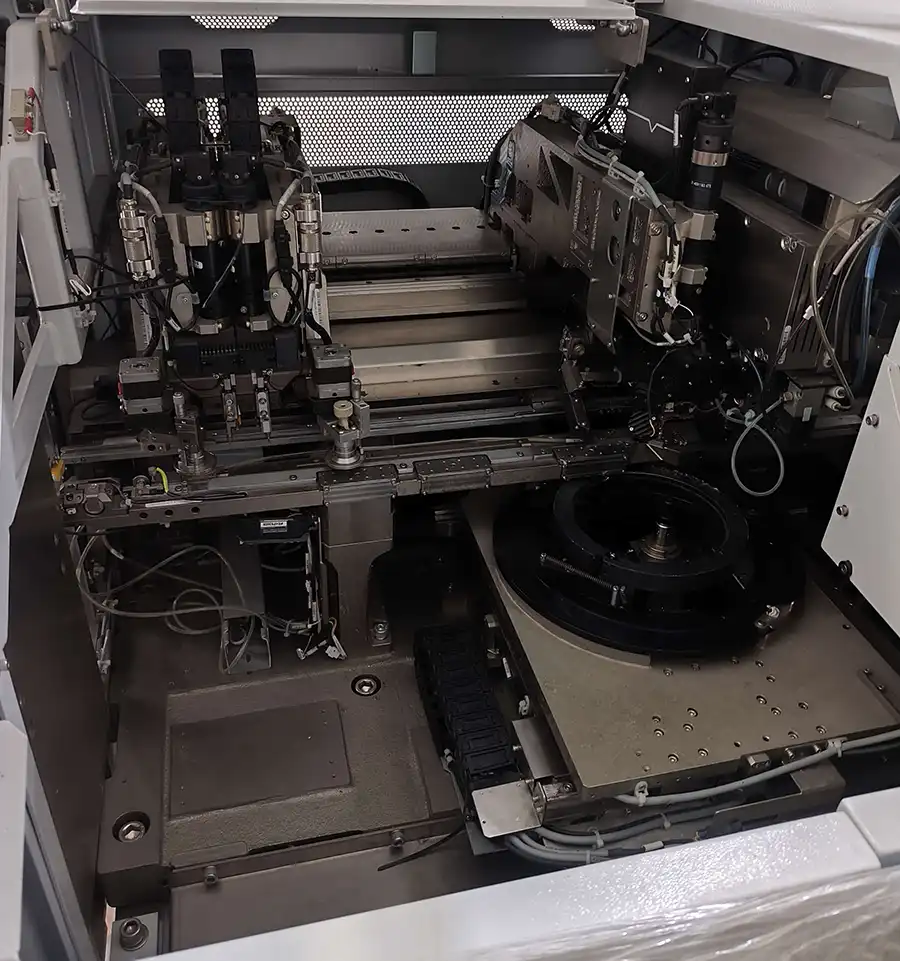
A production transfer should not begin by copying a package file and immediately running material. The original machine configuration, mechanical tools, process consumables, camera references and acceptance standards should first be documented.
Document die dimensions, wafer tape, lead-frame drawing, silver epoxy, cycle sequence, placement criteria and known process limits.
Compare the source and destination machines by input loader, work holder, wafer table, epoxy stations, cameras, bond head, software and output system.
Confirm collet geometry, ejector pin, ejector cap, magnetic anvil, window clamp, magazines and calibration tools for the intended package.
Teach track width, magazine positions, wafer coordinates, epoxy positions, pickup height, bond height and tooling clearances.
Verify focus and lighting before teaching wafer PR, lead-frame references, epoxy alignment, die recognition and post-bond inspection.
Start with limited sample quantities, inspect the complete process and release production only after the agreed acceptance criteria are met.
An AD830 Plus machine should be treated as a complete configured production system. These six areas determine whether the equipment can support the intended package.
Identify how unprocessed lead frames enter the machine and whether the loader fits the production magazine or stacked material.
Verify wafer size, frame dimensions, table movement, theta correction, expansion and optional automatic wafer loading.
Determine whether the machine uses dispensing, stamping or another configured silver-epoxy application arrangement.
Check the movement, vacuum, bond arm, force control and mechanical condition of the complete die-pick and placement system.
Confirm which cameras, lenses, lighting units and recognition functions are physically installed and operational.
Ensure the track, anvil, clamp, transfer components and output elevator support the actual lead-frame format.
Acceptance criteria should be agreed before sample testing begins. The test should evaluate repeatable production behavior rather than a single successful placement.
| Evaluation Area | What to Check | Why It Matters | Recommended Evidence |
|---|---|---|---|
| Material TransferInput, track and output movement | Magazine loading, pusher movement, indexing, support and output positioning | Mechanical interference or unstable transfer can stop production even when bonding is correct. | Continuous transfer trial using actual lead frames and magazines |
| Die ReleaseWafer tape and ejector behavior | Die separation, ejector height, die movement and signs of chipping or cracking | Release instability causes missing dies, damaged dies and placement variation. | Pickup trial across representative wafer locations |
| Vacuum PickupCollet and airflow response | Pickup consistency, vacuum stability, missing-die response and automatic re-pick | A dry cycle cannot reproduce the vacuum and tape-release behavior of real dies. | Recorded pickup results using production-equivalent dies |
| Epoxy DepositDispensing or stamping | Deposit location, volume consistency, shape, bridging and process repeatability | Unstable epoxy affects bond-line quality, contamination and downstream reliability. | Microscope inspection of repeated deposits before die placement |
| Die PlacementPosition and orientation | Offset, rotation, die seating, bond force and repeatability across the lead frame | Placement quality directly affects package assembly and downstream wire bonding. | Measured samples from multiple positions and repeated cycles |
| Vision InspectionPR stability | Image focus, lighting, reference recognition, search repeatability and reject response | A visible image alone does not confirm stable recognition or inspection performance. | Repeated PR searches and controlled defect samples |
Evaluate multiple cycles and material positions rather than approving one successful sequence.
Preserve the machine settings, tool numbers, material batch and inspection references.
Use optical or process inspection appropriate for the package and attachment material.
Agree who approves the sample and which measurements are required before production.
A machine alarm often identifies the stage where the process stopped, but not necessarily the underlying cause. Mechanical, material, tooling, vacuum, vision and recipe conditions should be checked together.
Investigate collet contamination, vacuum leakage, blocked passages, pickup height, ejector condition, wafer expansion, tape adhesion and airflow-detection settings before replacing the sensor.
Check ejector-pin geometry, die thickness, tape condition, vacuum level, collet dimensions, pickup force and the coordination between the ejector and bond arm.
Review epoxy viscosity, working time, pressure, needle or stamping tool, deposit height, tray level, delays and contamination around the process station.
Check camera focus, lens contamination, lighting, image contrast, reference selection, product movement and whether the correct package file is loaded.
Verify track width, magazine position, frame flatness, support anvil, clamp clearance, pusher alignment and accumulated epoxy or debris in the transport path.
Investigate vision references, wafer-theta correction, tool condition, die movement inside the collet, bond height, lead-frame support and mechanical calibration.
When replacing an existing AD830 Plus, matching only the manufacturer and model is insufficient. The replacement machine should be compared with the original machine at configuration, tooling, software, material-handling and utility level.
A structured comparison reduces the risk of receiving a machine that powers on correctly but cannot load the existing lead frame, use the current wafer ring, reproduce the epoxy process or accept the factory's existing tools.
Review the dedicated equipment page for used-machine availability, installed-module verification, functional testing, tooling confirmation, export packing and delivery support.
Common questions about AD830 naming, applications, configuration matching, production transfer and sample testing.
Send your die, wafer, lead-frame, silver-epoxy process and existing machine information for AD830 configuration review and equipment matching.
Why do so many people choose to work with GeekValue?
Our brand is spreading from city to city, and countless people have asked me, "What is GeekValue?" It stems from a simple vision: to empower Chinese innovation with cutting-edge technology. This is a brand spirit of continuous improvement, hidden in our relentless pursuit of detail and the delight of exceeding expectations with every delivery. This almost obsessive craftsmanship and dedication is not only the persistence of our founders, but also the essence and warmth of our brand. We hope you will start here and give us an opportunity to create perfection. Let us work together to create the next "zero defect" miracle.
DetailsContact a sales expert
Reach out to our sales team to explore customized solutions that perfectly meet your business needs and address any questions you may have.

© All Rights Reserved. Technical Support:TiaoQingCMS
