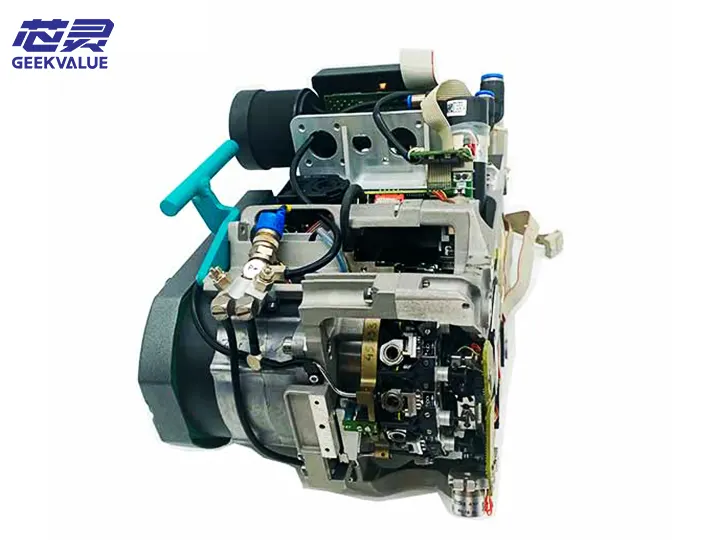
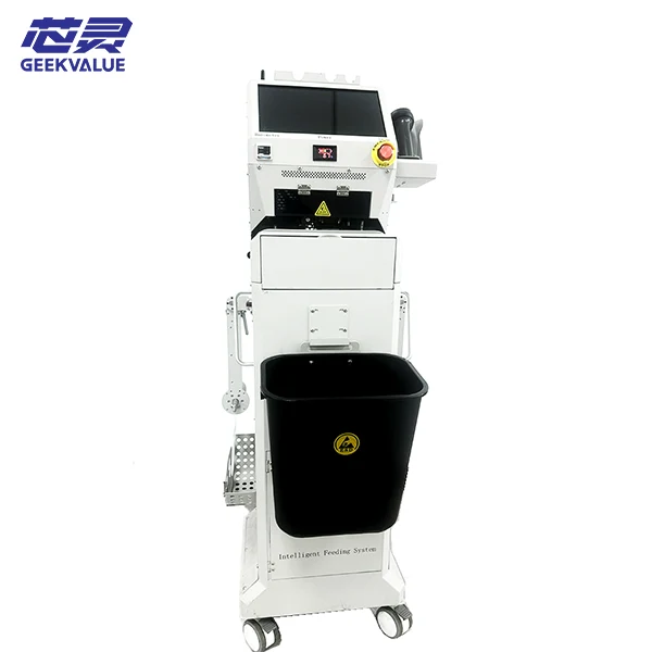
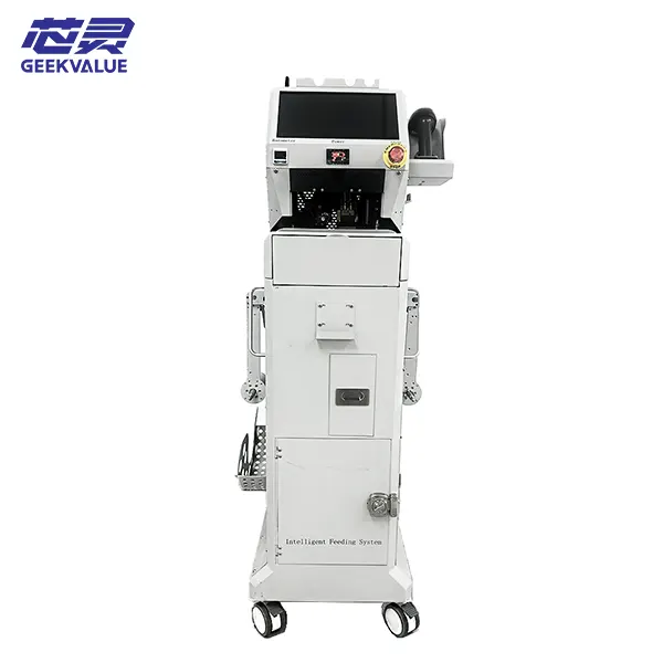
What Is the ASM E BY SIPLACE CP12 Placement Head?
The ASM E BY SIPLACE CP12 placement head is a high-precision surface-mount technology (SMT) component designed for use in SIPLACE X machines series . It features fast and accurate component placement capabilities, advanced vision systems, and reliable vacuum technology. This head supports a wide range of components—from microchips to larger SMDs—making it ideal for modern electronics production lines seeking both flexibility and speed.
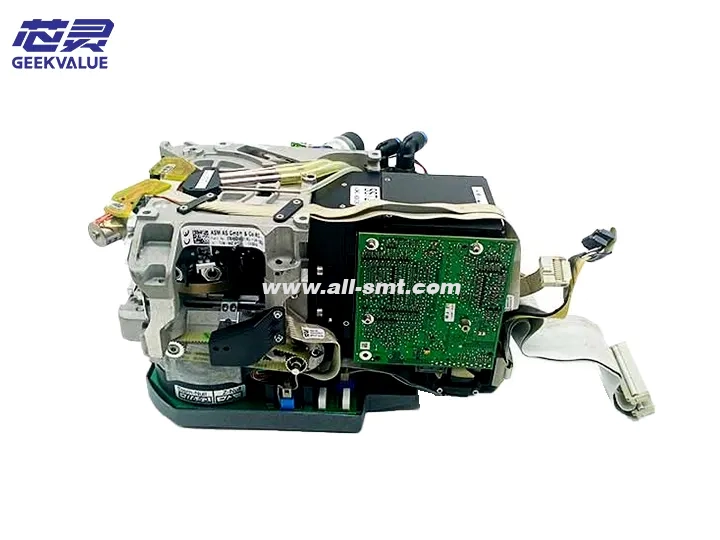
CP12 placement head Specifications
Applicable Models: SIPLACE X series SMT machines
Placement Speed: Up to 25,000 CPH (dependent on component type and machine configuration)
Placement Accuracy: ±25μm @ 3σ
Minimum Component Size: 0201 (0.25mm x 0.125mm)
Maximum Component Size: 30mm x 30mm (dependent on nozzle type)
Weight: Approximately 2.5 kg
Operating Temperature: 15–35°C
Humidity Range: 30–70% RH (non-condensing)
Structural Composition and Functions
1. Main Structure
Shell Frame: Made of aluminum alloy; provides structural integrity and protection
Spindle Drive System: Includes servo motor and precision bearings; enables Z-axis movement
Vacuum System: Comprises vacuum generator, vacuum sensor, and pipelines for component pickup
Vision System: High-resolution camera for component identification and alignment
Nozzle Clamping Mechanism: Allows quick nozzle replacement through mechanical fixation
Electronic Interface: Facilitates electrical communication with the host system
2. Core Accessories and Their Functions
| Accessory | Function |
|---|---|
| Servo Motor | Drives Z-axis and controls placement force |
| Vacuum Generator | Produces negative pressure for secure component pickup |
| Vacuum Sensor | Detects pickup and placement status |
| High-Resolution Camera | Captures images for component recognition and correction |
| Nozzle Clamp | Holds various nozzle sizes firmly for accurate placement |
| Linear Guide | Provides stability and precision for Z-axis travel |
| Position Encoder | Feeds back real-time position data for control accuracy |
| Temperature Sensor | Monitors placement head temperature to prevent overheating |
Usage Precautions
Installation and Removal
Always power off the machine before removing or installing the head
Use dedicated tools and follow the operation manual strictly
Confirm all electrical connectors are properly secured
Operating Environment
Keep the workspace clean to avoid dust interference
Maintain ambient temperature and humidity within defined limits
Prevent exposure to vibration or electromagnetic disturbances
Daily Operation Guidelines
Inspect vacuum system for leaks or pressure loss
Match nozzle types to component sizes accurately
Avoid extended periods of high-speed placement of large components
Safety Reminders
Never perform maintenance while the head is in motion
Routinely check cable condition for signs of wear
Stop operation immediately upon detecting unusual noise or vibration
Maintenance Schedule
1. Daily Maintenance
Wipe head surface with lint-free cloth to remove dust
Measure and verify vacuum pressure
Check each nozzle for clogs or wear when changing product lines
2. Weekly Maintenance
Apply grease to Z-axis guide rail using recommended lubricant
Tighten loose fasteners if any
Clean camera lens using proper tools
3. Monthly Maintenance
Inspect vacuum pipelines thoroughly
Calibrate Z-axis height and placement force
Test servo motor performance and response
4. Annual Maintenance
Replace all O-rings and sealing elements
Recalibrate the vision system completely
Check bearing wear and replace if necessary
Common Faults and Maintenance Solutions
1. Vacuum-Related Faults
Symptoms: High rate of component pickup failures
Possible Causes:
Low vacuum pressure
Blocked or worn nozzles
Leaky vacuum pipelines
Fixes:
Verify vacuum generator configuration
Clean or replace affected nozzles
Test pipelines using a leak detector
Fault Code: E1410 (Vacuum timeout)
Resolutions:
Check vacuum sensor connections
Calibrate the vacuum sensor
Inspect solenoid valve functionality
2. Mechanical Movement Faults
Symptoms: Abnormal or jerky Z-axis movement
Possible Causes:
Lack of lubrication on linear guide
Servo motor malfunction
Encoder signal failure
Fixes:
Clean and re-lubricate linear guide
Check motor signal and power supply
Inspect encoder connections and feedback accuracy
Fault Code: E1205 (Z-axis out of range)
Resolutions:
Inspect mechanical limit switch
Recalibrate Z-axis home position
Adjust drive control parameters
3. Vision System Faults
Symptoms: Component recognition errors
Possible Causes:
Dirty camera lens
Faulty lighting system
Corrupted calibration data
Fixes:
Clean lens with anti-static swabs
Confirm LED illumination levels
Perform complete system calibration
Fault Code: E2103 (Camera communication error)
Resolutions:
Check camera cable and port
Restart the vision module
Replace camera module if required
4. Electrical System Faults
Symptoms: Placement head not responding
Possible Causes:
Power supply failure
Damaged communication cable
Faulty controller board
Fixes:
Measure and confirm power input
Replace data cables and test continuity
Inspect control board LED status
Maintenance Best Practices
Follow systematic diagnostics: Begin with basic external checks, then move inward
Use fault codes to narrow troubleshooting scope
Double-check all parameters against technical documentation
Test with known working components to isolate issues
Keep detailed logs to track recurring problems
Prioritize preventive maintenance: It can prevent over 80% of known failures
Spare Parts Management Recommendations
Essential Spare Parts:
Full nozzle set (all specifications)
Vacuum generator module
O-ring and seal kit
Replacement servo motor
Backup camera module
Replacement Cycle Suggestions:
Nozzles: Every 3–6 months depending on usage frequency
O-rings: Annually
Vacuum Generator: Every 3–5 years or upon performance drop
Guide Rails: Every 3+ years or upon visible wear
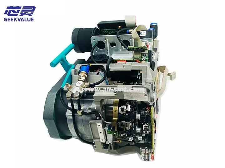
Proper use and maintenance of the ASM E BY SIPLACE CP12 placement head is essential to maintain optimal performance, reduce downtime, and improve product quality. Following a structured maintenance schedule and responding promptly to fault codes will ensure long-term reliability and efficiency in high-volume SMT production environments.
For professional support, spare parts, and consulting services, contact GEEKVALUE— your trusted partner in SMT excellence.
E BY SIPLACE CP12 placement head FAQ
-
What makes the CP12 different from other SIPLACE heads?
The CP12 offers a balance of high-speed placement (up to 25,000 CPH) and ±25μm accuracy, making it versatile for both fine-pitch and standard components.
-
Can this head be installed on any SIPLACE X series model?
Yes, the CP12 head is compatible with all SIPLACE X series machines. Please verify your machine’s firmware version for compatibility.
-
How often should I replace the nozzle or perform maintenance?
Nozzles should typically be inspected every 3–6 months. Preventive maintenance is recommended daily, weekly, monthly, and annually based on the schedule provided.
-
What is the most common cause of vacuum failure?
Most vacuum failures are due to nozzle clogging, pipeline leaks, or deteriorated seals. Regular inspection can prevent these issues.
-
Can I purchase spare parts directly from ReissDisplay?
Yes. We offer genuine spare parts, including nozzles, servo motors, and vacuum modules. Contact our support team for a custom quote.

