1. Product Overview and Technical Specifications
1.1 Basic Parameters
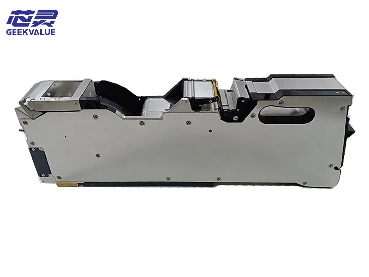
Model: 00141397
Type: Electric Feeder with Sensor
Applicable Strip Width: 72mm (Compatible with 68-72mm)
Feeding Pitch: 4/8/12/16/20/24mm Programmable
Maximum Component Height: 15mm
Strip Thickness Range: 0.3-2.0mm
Dimensions: 320mm×120mm×95mm
Weight: 3.5kg
Service Life: ≥30 million feeding cycles
Protection Level: IP54
1.2 Electrical Parameters
Working Voltage: 24VDC±10%
Power Consumption: 25W in Normal Mode, 50W in Peak Mode
Communication Interface: CAN Bus (Compatible with RS-485)
Sensor Type: High Resolution Optical Sensor + Hall Sensor
Response Time: <2ms
1.3 Applicable Models
SIPLACE X series (X4i, X4s)
SIPLACE TX series
SIPLACE SX series
SIPLACE D series (adapter bracket required)
II. Mechanical structure and working principle
2.1 Core mechanical components
Drive system:
High torque stepper motor (1.8° step angle)
Precision planetary gearbox (reduction ratio 20:1)
Dual cam feeding mechanism
Guide system:
Reinforced dual linear guide rails (adjustable width)
Ceramic coated wear-resistant bushings
Segmented pressing device (8 pressure points)
Sensor system:
Main sensor: 5 million pixel CMOS optical sensor
Auxiliary sensor: Differential Hall sensor array
Ambient light anti-interference system
Tape handling system:
Automatic stripping device (adjustable force)
Waste tape collection guide
Anti-rebound mechanism
2.2 Working principle
Power transmission:
Controller sends pulse signal to stepper motor driver
Gearbox drives feeding cam
Precise positioning:
Main optical sensor reads material belt positioning hole
Hall sensor verifies mechanical position
Closed-loop control system real-time adjustment
Status monitoring:
Material belt remaining quantity detection (10 component warning in advance)
Component existence check
Feeding force monitoring
Data interaction:
Real-time upper material count
Store the latest 1000 alarm records
Support remote diagnosis
III. Performance characteristics and technical advantages
3.1 Core performance indicators
Feeding accuracy: ±0.03mm (@23±1℃)
Maximum feeding speed: 35 times/minute (24mm step)
Load capacity: supports 5kg tray
Temperature stability: ±0.01mm/℃
Repeat positioning accuracy: ±0.02mm (3σ)
3.2 Innovative technology highlights
Intelligent feeding control:
Adaptive learning algorithm (memorizes different material characteristics)
Automatic compensation for mechanical wear
Multiple sensor systems:
Triple redundant detection mechanism (optical + magnetic + mechanical)
Anti-pollution optical channel design
Modular design:
Quick-release feeding module (replacement time <2 minutes)
Independent replaceable sensor module
Energy efficiency optimization
Dynamic power regulation
Standby power consumption <1W
IV. Application scenarios and production line value
4.1 Typical application components
Large-size electrolytic capacitors (diameter ≥18mm)
Power modules (IGBT, MOSFET, etc.)
Large connectors
Transformer/inductor components
Heat dissipation module
4.2 Production line value
High precision guarantee:
Meet automotive electronics Grade-1 standard
Support all sizes above 01005 components
Efficiency improvement:
Replacement time <15 seconds
Intelligent early warning reduces unplanned downtime
Intelligent management:
Component traceability data collection
Predictive maintenance support
Cost optimization:
Energy saving 40% compared to pneumatic feeder
Maintenance interval extended by 3 times
V. Installation and operation guide
5.1 Installation process
Mechanical installation:
Align the guide groove of the feeder station of the placement machine
Push it into the automatic locking position (green indicator light on)
Electrical connection:
Connect 24VDC power supply (pay attention to polarity)
Insert CAN bus communication cable
System identification:
The placement machine automatically identifies the feeder type
Assign station number and load parameters
5.2 Operation points
Tape loading:
Open the pressing cover (press the blue buttons on both sides)
Ensure that the tape enters the guide groove straightly
Set the correct tape width (scale indication)
2 Parameter settings:
python
# Typical parameter setting example
{
"feed_pitch": 16, # Feeding pitch (mm)
"peel_force": 3, # Peeling force (N)
"sensitivity": 85, # Sensor sensitivity (%)
"pre_alarm": 10, # Number of early warnings
"speed_profile": 2 # Speed profile mode
}
Calibration process:
Perform automatic calibration (standard calibration tape required)
Manually verify the first 3 feeding positions
Save calibration parameters
VI. Maintenance system
6.1 Daily maintenance
Cleaning and maintenance:
Vacuum the guide area daily
Clean the sensor window with IPA every week (concentration 99.7%)
Lubrication management:
Lubricate after every 500,000 feedings:
Linear guide: Kluber ISOFLEX NBU15
Gear set: Molykote PG-65
6.2 Regular maintenance (quarterly)
Comprehensive inspection:
Measure rail wear (maximum allowable clearance 0.05mm)
Test motor current (rated value 1.2A±10%)
In-depth maintenance:
Replace worn bushing (if loose >0.1mm)
Calibrate sensor reference position
Performance verification:
Use standard test tape
Measure cumulative error after 100 continuous feeds
VII. Common fault diagnosis and treatment
7.1 Fault code analysis
Code Description Possible cause Solution
E721 Feeding timeout 1. Mechanical jamming
2. Motor failure 1. Check tape path
2. Test motor windings
E722 Sensor abnormality 1. Contamination
2. Wiring failure 1. Clean sensor
2. Check connector
E723 Communication interruption 1. Cable damage
2. Interface oxidation 1. Replace communication cable
2. Process contacts
E724 Position deviation is too large 1. Parameter error
2. Mechanical wear 1. Recalibrate
2. Check the gear set
E725 temperature warning 1. Overheating of the environment
2. Poor heat dissipation 1. Improve ventilation
2. Check the fan
7.2 Replacement of key components
Replacement of the feed module:
Remove 4 T8 screws
Disconnect the motor connector
Be careful to maintain the calibration position
Replacement of the sensor module:
Use anti-static tools
Perform optical calibration after replacement
Verify the alignment of the Hall sensor
VIII. Technology evolution and improvement suggestions
8.1 Version iteration
Gen1 (2015): Basic 72mm feeder
Gen2 (2018): Add intelligent sensing system
Gen3 (2021): Current model (CAN bus version)
8.2 Optimization suggestions
Parameter optimization:
Establish parameter templates for different material strips
Enable adaptive learning function
Spare parts strategy:
Standard key components:
Feeding gear set (P/N: 00141398)
Sensor module (P/N: 00141399)
Upgrade options:
High resolution version (5μm accuracy)
High temperature model (supports 85℃ environment)
IX. Comparison with other specifications of feeders
Parameters 72mm feeder 00141397 52mm feeder 32mm mechanical feeder
Maximum material strip width 72mm 52mm 32mm
Feeding accuracy ±0.03mm ±0.05mm ±0.1mm
Sensing function Multi-sensor system Basic sensor None
Maximum component height 15mm 10mm 8mm
Communication interface CAN bus RS-485 None
X. Summary and Outlook
ASM 72mm sensor feeder 00141397 represents the highest level of current large-size component feeding technology. Its core value lies in:
Ultra-large size processing capability: fills the technical gap of 50-100mm tape feeding
Military-grade reliability: MTBF>50,000 hours
High degree of intelligence: provides complete data interface for Industry 4.0
Future development direction:
Integrated AI visual assisted positioning
Wireless power supply and communication
Application of self-healing materials
Best practice recommendations:
Establish a preventive maintenance plan
Regularly back up parameter settings
Maintain 15% spare parts redundancy
This equipment is particularly suitable for:
New energy automotive electronics manufacturing
Industrial power module production
High-power LED packaging
Aerospace electronics assembly
Through standardized use and scientific maintenance, this feeder can ensure 7×24 hours of continuous and stable operation, providing reliable ultra-large component feeding solutions for high-end electronics manufacturing.