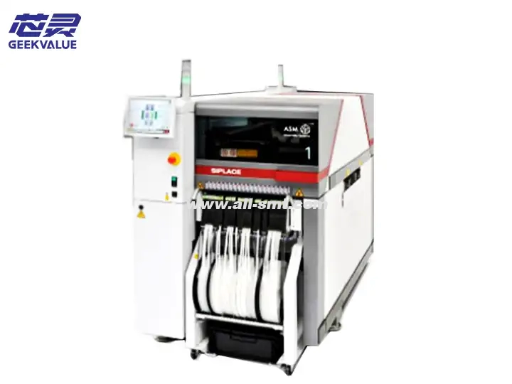
ASM TX1 is a high-precision modular placement machine launched by ASM Pacific Technology Co., Ltd., designed for high-mix, high-precision placement needs in modern electronic manufacturing, and suitable for a full range of placement from 0201 components to large special-shaped components.
1.2 Technical Specifications
Parameter Category Technical Indicators
Placement Accuracy ±25μm @3σ (chip) / ±35μm @3σ (QFP)
Maximum Placement Speed 25,000 CPH (under optimal conditions)
Component Processing Range 0201~150×150mm (L×W)
Maximum Component Height 25mm
Feeder Capacity Up to 120 8mm Feeder Stations
Board Size 50×50mm ~ 510×460mm (L×W)
Machine Size 1,450×1,350×1,450mm (L×W×H)
Weight About 1,800kg
Power Requirements 400VAC 3-phase 50/60Hz 15kVA
Compressed Air Requirements 5.5~6.5bar, Clean and Dry Air
II. Working Principle and System Architecture
2.1 Core working principle
Motion control:
Linear motor drives X-Y axis
High-precision grating scale closed-loop control (resolution 0.1μm)
Vision system:
Upward camera: 30MP global shutter CMOS
Downward camera: 15MP+ laser height measurement
On-the-fly centering technology
Placement process:
Text
PCB positioning → component picking → on-the-fly centering → height detection → precise placement → quality verification
2.2 System architecture
Mechanical system:
Cast iron base (thermal expansion coefficient <0.8μm/m℃)
Carbon fiber beam (weight reduction of 30%)
Electrical system:
Distributed I/O control
Real-time industrial Ethernet (EtherCAT)
Software system:
SIPLACE OS is based on Windows 10 IoT
Supports OPC UA communication protocol
III. Core advantages and technological innovation
3.1 Market competitive advantage
Balance between precision and speed:
Unique "SoftTouch" placement technology reduces component bounce
Dynamic Z-axis control achieves ±5μm height accuracy
Flexible production capacity:
Quick line change (<15 minutes full machine model switching)
Mixed material tray and reel tape used simultaneously
Intelligent calibration system:
Automatic laser calibration of nozzle position
Temperature compensation algorithm (±0.5μm/℃)
3.2 Technical innovation points
Intelligent feeding system:
Feida health status monitoring
Predictive feeding maintenance
Advanced motion control:
Third-order motion curve planning
Vibration suppression algorithm
Quality assurance system:
Online SPC statistical analysis
3D solder paste detection interface
IV. Functional features and application value
4.1 Core functions
High-precision placement:
Support 01005 component placement
0.3mm fine pitch QFP processing capability
Intelligent optimization:
Automatic placement sequence optimization
Nozzle automatic distribution system
Process monitoring:
Real-time placement force monitoring
Automatic component polarity verification
4.2 Production line value
Efficiency improvement: 20% faster than the previous generation of models
Quality improvement: first-piece pass rate>99.5%
Cost reduction: line change time reduced by 40%
Flexibility enhancement: Support NPI fast import
V. Common errors and processing solutions
5.1 Error code classification and processing
Code series Fault category Typical processing measures
1xxx Mechanical system error Check motion mechanism/lubrication/mechanical limit
2xxx Vision system error Clean lens/calibrate light source/check camera connection
3xxx Feeding system error Verify feeder status/check material belt/sensor calibration
4xxx Vacuum system error Detect vacuum pipeline/clean nozzle/check solenoid valve
5xxx Control system error Restart the controller/check FPGA status/update firmware
5.2 Typical error cases
E1205: X-axis position deviation:
Possible cause: grating scale contamination/linear motor failure
Handling: Clean the grating scale → calibrate the origin → test the motor current
E2310: Downward camera out of focus:
Possible cause: Z-axis height sensor drift
Handling: Perform automatic focus calibration → Check laser sensor
E3108: Feeder communication interruption:
Possible cause: CAN bus terminal resistor failure
Handling: Check the terminal resistor (120Ω) → Test the bus waveform
VI. Maintenance system
6.1 Preventive maintenance plan
Cycle Maintenance items Standard method
Daily Machine surface cleaning Dust-free cloth + IPA cleaning
Weekly Motion guide rail inspection Manual movement inspection smoothness
Monthly Comprehensive lubrication Use special grease (Kluber ISOFLEX)
Quarterly Accuracy verification Use standard calibration board
Semi-annual Electrical system inspection Insulation test/ground resistance test
Yearly Comprehensive maintenance Manufacturer professional technical service
6.2 Maintenance of key components
Linear guide rail:
Cleaning: Use lint-free cloth + special cleaning agent
Lubrication: Lithium-based grease, replenish every 3 months
Vacuum system:
Filter: Replace every 500 hours
Pipeline: Leak detection every month
Optical system:
Lens cleaning: Use lens pen every week
Light source calibration: Monthly brightness detection
VII. Common faults and maintenance ideas
7.1 Fault diagnosis process
text
Fault phenomenon → HMI error confirmation → Subsystem isolation test → Signal measurement → Component replacement → Function verification
7.2 Typical troubleshooting
Placement offset:
Inspection process: camera calibration → nozzle wear → PCB clamping
Maintenance plan: recalibrate → replace nozzle → adjust fixture
High throw rate:
Inspection process: vacuum detection → component height → feeding position
Maintenance plan: clean nozzle → adjust pick-up height → calibrate feeder
Machine abnormal noise:
Inspection process: linear guide → belt tension → motor bearing
Maintenance plan: clean guide → adjust tension → replace bearing
VIII. Maintenance and upgrade suggestions
8.1 Gradual maintenance strategy
Level Fault type Response time Required skills
L1 Operational problems Immediate Operator level
L2 Simple hardware failure Within 4 hours Junior technician
L3 Complex system failure Within 24 hours Senior engineer
L4 Core component failure Within 48 hours Manufacturer professional technical support
8.2 Upgrade optimization suggestions
Hardware upgrade:
Optional high-precision placement head (±15μm)
Upgrade to 10MP high-speed camera
Software upgrade:
Install Advanced Process Control suite
Enable AI placement optimization algorithm
System integration:
Interface with MES/ERP system
Realize remote diagnosis function
IX. Technology evolution and market positioning
9.1 Product iteration route
2018: Release of TX1 basic version
2020: Upgrade motion control system
2022: Integrated intelligent feeding system
2024 (planning): AI visual enhanced version
9.2 Competitive product comparison
Parameters ASM TX1 Competitive product A Competitive product B
Placement accuracy ±25μm ±30μm ±35μm
Maximum speed 25k CPH 23k CPH 20k CPH
Line change time <15 minutes 25 minutes 30 minutes
Energy consumption efficiency 0.9kW/kCPH 1.2kW/kCPH 1.5kW/kCPH
Intelligence level Advanced Intermediate Basic
X. Summary and best practices
10.1 Recommendations for use
Environmental control:
Temperature: 23±2℃
Humidity: 50±10% RH
Vibration: <0.5G (5-200Hz)
Operational specifications:
Preheat for 15 minutes daily
Back up machine parameters regularly
Use original consumables
Personnel training:
Certified operator training (3 days)
Advanced maintenance course (5 days)
10.2 Application prospects
ASM TX1 is particularly suitable for:
Automotive electronics manufacturing
High-end consumer electronics
Medical equipment electronic assembly
Aerospace electronics
5G communication equipment
Through scientific maintenance management and technological innovation, TX1 can ensure:
Equipment utilization rate>90%
Mean time between failures>5,000 hours
Comprehensive operating cost reduction of 25%
It is recommended that users establish a complete preventive maintenance system and maintain close cooperation with ASM technical support to give full play to the performance of the equipment and obtain the best return on investment.


