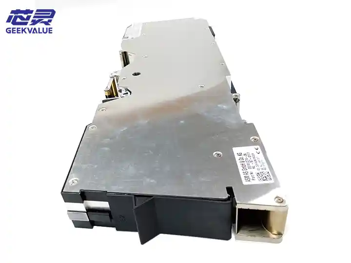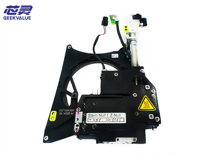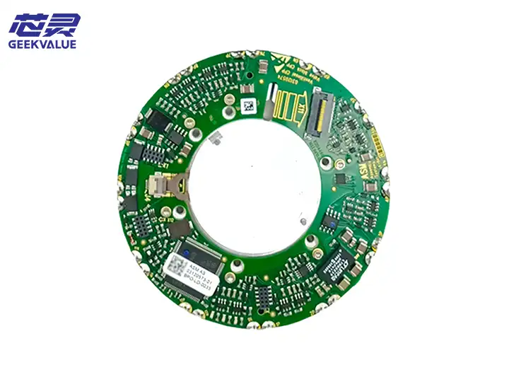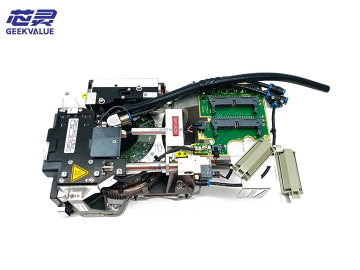
The CPP (Component Placement Head) work head is the core component of the ASM placement machine, responsible for picking up components from the feeder and accurately placing them on the PCB board. The CPP work head of ASM (now Siemens Electronic Assembly Systems Division) enjoys a high reputation in the SMT industry for its high precision, high speed and high reliability.
2. Structural composition
1. Mechanical structure
Spindle system: includes servo motor, high-precision ball screw and linear guide
Nozzle rod: replaceable nozzle mounting rod, usually with 12 or 16 stations
Vacuum system: includes vacuum generator, vacuum sensor and vacuum channel
Centering system: visual system and mechanical centering claw for component centering
Z-axis drive: servo or pneumatic system to control placement height
θ-axis rotation: stepper or servo motor for component angle rotation
2. Electronic system
Encoder system: high-resolution encoder for precise positioning
Sensor system:
Vacuum sensor
Height sensor
Position sensor
Temperature sensor
Control board: dedicated control circuit board
3. Auxiliary system
Nozzle replacement device: automatic or semi-automatic nozzle replacement mechanism
Cleaning system: automatic nozzle cleaning device
Lubrication system: automatic lubrication device
III. Functions and effects
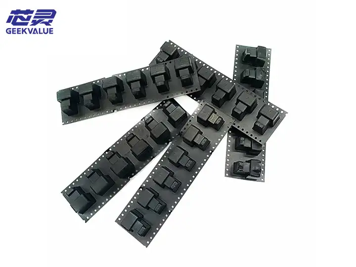
Component picking: Accurately pick up SMD components of various specifications from the feeder
Component detection: Check whether the component is picked up normally through vacuum
Component centering: Correct the position and angle of the component by visual or mechanical means
Precise placement: Accurately place the component on the specified position of the PCB with the set pressure and angle
Nozzle management: Automatically identify and replace nozzles of different specifications
Process monitoring: Real-time monitoring of various parameters during the placement process
IV. Common errors and fault information
1. Mechanical failures
E101: Z-axis over-limit error - Z-axis movement exceeds the set range
E205: Nozzle rod stuck - Nozzle rod cannot move up and down normally
E307: θ-axis positioning error - Rotation axis cannot reach the specified angle
2. Vacuum system failure
E401: Vacuum establishment failure - Unable to establish sufficient vacuum for picking
E402: Vacuum leak - vacuum drops too quickly after picking
E403: Vacuum release failure - unable to release component after mounting
3. Sensor failure
E501: Height sensor abnormality
E502: Encoder signal loss
E503: Temperature sensor out of limit
4. Electronic system failure
E601: Servo drive failure
E602: Control board communication interruption
E603: Power supply voltage abnormality
V. Maintenance methods
1. Daily maintenance
Cleaning work:
Clean the nozzle and nozzle rod daily
Clean the vacuum filter
Remove dust and residue around the work head
Lubrication work:
Lubricate the guide rails and lead screws regularly according to the manual requirements
Use the specified type of grease
Inspection work:
Check whether each sensor is working properly
Check whether the vacuum system pressure is normal
Check whether there are abnormal sounds in each moving part
2. Regular maintenance
Monthly maintenance:
Thoroughly clean the entire work head
Check and replace worn O-rings
Calibrate the position accuracy of each axis
Quarterly maintenance:
Replace the vacuum filter
Check and adjust the belt tension
Fully calibrate the visual system
Annual maintenance:
Replace worn mechanical parts
Fully check the electrical system
Perform comprehensive performance test
VI. Maintenance ideas
1. Fault diagnosis process
Observe the phenomenon: record the fault code and machine status
Analyze possible causes: List possible causes according to the manual and experience
Step-by-step troubleshooting: Check one by one from simple to complex
Verify and repair: Test and verify after repair
2. Common fault handling
Placement offset:
Check visual system calibration
Check mechanical centering mechanism
Check encoder signal
Component pickup failure:
Check vacuum system
Check nozzle selection and wear
Check feeder position
Abnormal movement:
Check servo drive and motor
Check mechanical transmission components
Check position sensor
3. Maintenance precautions
Safety first: Perform mechanical maintenance after power off
Anti-static measures: Take anti-static protection when handling electronic components
Use genuine spare parts: Try to use original spare parts
Record the maintenance process: Record the maintenance steps and replacement parts in detail
VII. Technology Development Trends
Higher speed: adopt lighter design and faster drive system
Higher precision: application of nano-positioning technology
Intelligence: integrate more sensors to achieve predictive maintenance
Modular design: convenient for quick replacement and repair
Multi-function integration: integrate more detection functions into the work head
Through the above comprehensive understanding of the structure, function, maintenance and repair methods of the CPP work head, you can better use and maintain the ASM placement machine to ensure the stable and efficient operation of the production line.