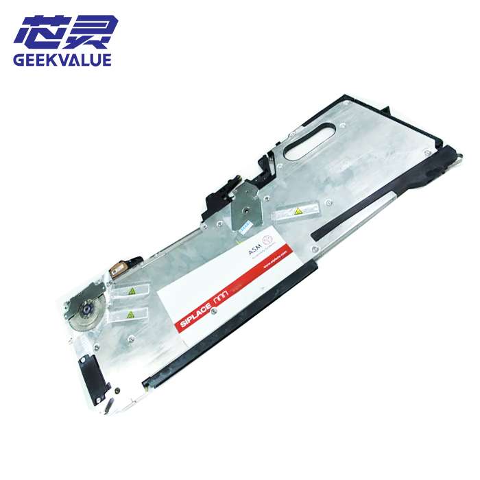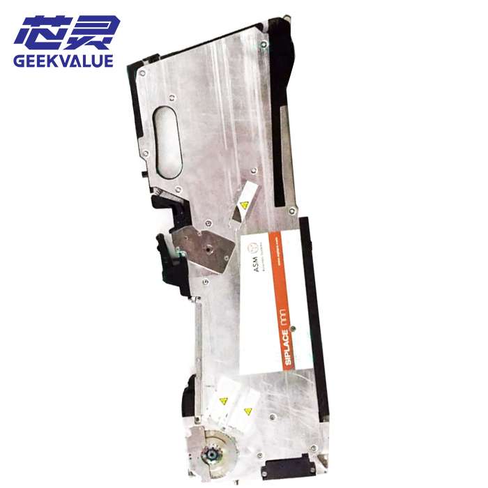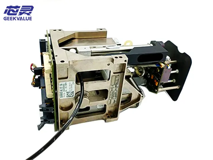
The TH IC (Through Hole Integrated Circuit) head is a key component in the ASM placement machine, specifically designed for inserting through-hole components (such as DIP ICs, connectors, electrolytic capacitors, etc.). It combines high-precision mechanical alignment and stable insertion force control, suitable for high-mix, high-precision through-hole component placement needs.
2. Structural composition
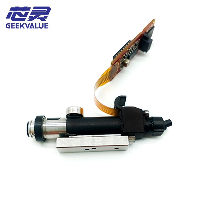
1. Mechanical structure
Z-axis drive system: servo motor + ball screw, control insertion depth and pressure
Clamping mechanism: adjustable clamping force, suitable for THT (through-hole technology) components of different sizes
Centering mechanism: optical or mechanical alignment system to ensure that the pins are aligned with the PCB holes
Feeding interface: can be docked with a vibration feeder or a tube feeder to achieve stable feeding
2. Electronic system
Servo control system: high-precision control of insertion position and force
Force feedback sensor: monitors insertion pressure to prevent damage to components or PCBs
Vision system (optional): used for pin detection and alignment compensation
3. Auxiliary system
Automatic clamp replacement device (supported by some high-end models)
Self-cleaning mechanism: prevent flux residue from affecting clamping accuracy
Lubrication system: ensure long-term operation stability
3. SMT patch head specifications
Parameter Specification range Description
Applicable components: DIP IC, connector, electrolytic capacitor, etc. Pin spacing ≥2.54mm (standard THT)
Installation accuracy ±0.05mm Optical alignment can be increased to ±0.02mm
Insertion force range 0.5N~10N Programmable control to prevent PCB damage
Maximum component size 50mm×50mm (depending on the model) Some models support larger sizes
Insertion speed 800~1500CPH (depending on the complexity of the component) High-speed models can reach 2000CPH
IV. Advantages and features
1. High-precision insertion
Adopt servo control + force feedback to ensure that the pins are accurately inserted into the PCB holes to avoid bending or misalignment.
Optional visual alignment to meet the needs of high-density PCB boards.
2. Stable and reliable clamping force
Programmable pressure control to prevent component damage or PCB pad damage.
Adaptive gripper design, compatible with THT components of different sizes.
3. High compatibility
Supports multiple feeding methods (tube type, vibration disc type, tray type, etc.).
The fixture can be quickly replaced to reduce line change time.
4. Intelligent monitoring
Real-time monitoring of plug-in pressure, automatic alarm and pause when abnormal.
Equipped with self-diagnosis function to reduce downtime.
V. Common errors and fault information
1. Mechanical failure
Error code Fault description Possible cause
E110 Z axis overtravel error Mechanical limit abnormality/servo parameter error
E205 Gripper not closed/stuck Gripper mechanism worn/insufficient air pressure
E310 Insertion force exceeded Pressure sensor failure/component size mismatch
2. Sensor failure
Error code Fault description Possible cause
E401 Abnormal force feedback signal Sensor damage/signal interference
E502 Visual alignment failure Lens contamination/light source failure
E603 Encoder signal lost Cable loose/encoder damaged
3. Feeding failure
Error code Fault description Possible cause
E701 Component not sucked up Feeder not in place/vacuum insufficient
E702 Pin deformation/missing Feeding vibration is too large/component quality is poor
VI. Maintenance method
1. Daily maintenance
Cleaning the gripper and nozzle: Wipe with dust-free cloth + IPA (isopropyl alcohol) to prevent flux residue.
Check air pressure: Make sure it is stable (usually 0.5~0.7MPa).
Lubricate guide rails/screws: Use specified grease, once a month.
2. Regular maintenance (every 3~6 months)
Check jaw wear: Replace worn clamping parts.
Calibrate force sensor: Ensure accurate insertion pressure.
Check servo motor: Test running stability to avoid jitter.
3. Annual maintenance
Fully calibrate mechanical accuracy (Z-axis travel, centering mechanism, etc.).
Replace aging air pipes/cables.
Upgrade firmware (if new version is available).
VII. Troubleshooting methods
1. Plug-in position offset
Possible causes: misalignment/PCB positioning deviation
Solution:
Recalibrate the visual system
Check if the PCB fixture is loose
2. Abnormal plug-in pressure (alarm E310)
Possible causes: pressure sensor failure/component size mismatch
Solution:
Check if component specifications match
Recalibrate the force sensor
3. The fixture cannot be closed (alarm E205)
Possible causes: insufficient air pressure/solenoid valve failure
Solution:
Check if the air line is leaking
Clean or replace the solenoid valve
8. Conclusion
ASM's TH IC head is an ideal choice for through-hole component insertion due to its high precision, stability and intelligent monitoring capabilities. Through proper maintenance and troubleshooting, production efficiency and yield can be greatly improved. For high-mix production environments, regular calibration and replacement of wearing parts are recommended to ensure long-term stable operation.